MerolaAlba
Newbie
Hello Catia Community,
I have an issue I've been dealing for some time and need help.
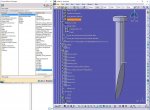
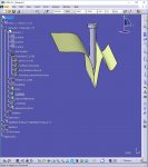
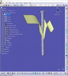
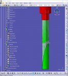
I have attached several images that follow the points described below (apologies if everything seems overly explained, I am new to CATIA and am merely explaining to make sure that i am not making any mistakes):
1
there is a part that the user is going to split the ejectors with
2
the user inserts, in the correct position via Mold Tooling Design, as many ejectors as required (i'm going to use one to simplify the matter, further explaining the issue i'm dealing with and show in detail what i've done so far). Because the ejector is parameterized the user can choose a desired length and diameter (i'm choosing one manually although with a catalog this will not be done unless required)
3
the ejector is split, via the split component, several things happened:
2 geometrical set have been created:
1st - "external references" with the result of the ejector split
2nd - "Geometrical Set.4" with a BaseBody Line leading to the result of the ejector split
4
I have managed to create the Max: using the rule "ejector length adjustment" and reaction "ejector length adjustment" 3 extremums (x,y,z) and a line that were previously created activate when a set parameter is changed, automatically giving me the length of the line and adjusting the actual ejector to the closest superior one to the line's length.
5
therefore i need to automatically create:
1st - the Min (i manually created it "Extremum.5" to show the desired position in this example at the actual geometrical spot).
2nd - measure from the Min to the Base, i manually created a plane "Plane.3", line "Line.4" and have measured it.
3rd - alter the DrillHole that is currently from the BaseBody Line to the newly created line.
Any help you may give me is greatly appreciated.
Kind Regards,


