Continue to Site

Welcome to 3DCADForums

Join our CAD community forums where over 25,000 users interact to solve day to day problems and share ideas. We encourage you to visit, invite you to participate and look forward to your input and opinions. Acrobat 3D, AutoCAD, Catia, Inventor, IronCAD, Creo, Pro/ENGINEER, Solid Edge, SolidWorks, and others.

Compound Angle Hole - Catia

Sheeaun

New member
I'm working on a practice part in college with a compound angle hole. The goal here is to practice surfacing so I can't use any sketches, not even for reference. I will attach the print to this post for reference. The center line of the hole is called out as 17 degrees up from the bottom and angled 50 degrees from the front face. No matter what I do, either the counterbore cuts into the top surface or the hole cuts a piece out of the bottom surface and I've been told neither of these things should happen.

Any help would be greatly appreciated.
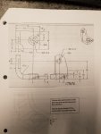
Print for practice.jpgScreenshot (1).jpgScreenshot (2).jpg
 
one way to get the centerline: create two Planes (one at 17° off the bottom face, and the other at 50°), and then Intersect the planes for the centerline. Just make sure both planes pass through the centerpoint on the right side (based on the 19mm and 8mm dimensions)
 
Last edited:
one way to get the centerline: create two Planes (one at 17° off the bottom face, and the other at 50°), and then Intersect the planes for the centerline. Just make sure both planes pass through the centerpoint on the right side (based on the 19mm and 8mm dimensions)

can you please show me the work around to make the hole?
 
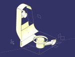
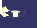
I used the drawing above for reference and was able to create a "wireframe and surface" model as you can see in my image below. (I did this with no Solids, and no Sketches)
help1.jpg

I only added surfaces where the face was curved (not planar). These flat, planar faces can be added with FILL surfaces, and holes can be removed with Split.

Although this is a fairly difficult assignment; you will learn a lot of wireframe and surfacing techniques by doing this. I hope your instructor explains all the steps thoroughly. (When I taught CATIA, I had a similar exercise with intersecting surfaces that I had to explain to each class.) If nothing else, it makes you appreciate solids modeling!

There are two things I would like to point out, before I answer your question about the counterbored hole:

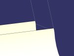
1. The R13 fillet actually ends 1mm above the 25mm flat on the right side. It's hard to see, but the R13 fillet surface will need to be trimmed in the corner. Same with the outside surface.
help2.jpg


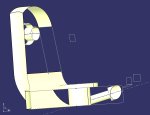
2. When I added the counterbored hole at the compound angle, the hole broke through the bottom face, which is not supposed to happen according to the original post. So, I changed the hole size from Ø8 to Ø6 to avoid this.
help3.jpg
 
Last edited:
can you please show me the work around to make the hole?

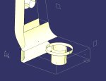
Here's how I made the counterbored hole:

1. I modeled the rest of the part, leaving the counterbored hole for last. Based on the drawing provided above, the dimension of the hole is: "1 HOLE Ø8 CBORE Ø10 DEPTH 5"
step1.jpg

2. based on the axis system shown in the images, I added a Point with coordinates x=70, y=27+19, z=8 to define the centerpoint of the hole

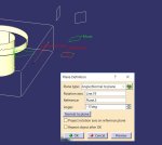
3. I added a plane at the front of the part (x=70), and another plane at the height of the point (z=8). These will be reference planes for the next step
step2.jpg

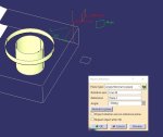
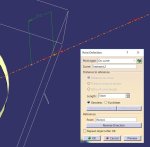
4. referring to the top view in the drawing, I added a vertical line through the point. I then added an angled plane through the vertical line at an angle of 50°. (+50° looked wrong, so I used -50° instead) And I moved this plane so I could easily see it.
step 3.JPG

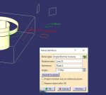
5. I repeated step 4, with a horizontal line and I added a second plane at an angle of -17°
step4.JPG

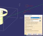
6. Intersecting these two planes will create the centerline of the counterbored hole. I changed the line Properties to make this line easy to identify. Rotate the model to look at it from the top and side to verify the line's compound angles are correct.
step5.JPG

7. Now I added a point for the depth of the counterbore (5mm) from the centerpoint.
step6.JPG

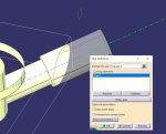
8. Then I added a plane normal to the curve, as shown above. I also Hide the lines and planes that were cluttering up the screen.

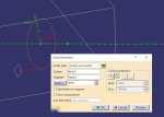
9. Using the normal plane as the support, I added a circle for the hole size (R=8/2)
step7.JPG

10. then I added a second circle (same centerpoint, same support) with a R=10/2 for the counterbore.

11. Extrude both of these circles to get the cylindrical surfaces of the counterbored hole. The length isn't important as long as both surfaces extend beyond their limits
step8.JPG
As you can see, the Ø8 cylinder extends down and breaks through the bottom of the part. We'll keep the 4mm radius to follow the dimension on the drawing and model the actual shape.

12. Split the Ø10 cylinder with the plane at the front of the part (the plane might be hidden). Click on the OTHER SIDE button, if you get the wrong side
step9.JPG

almost done, but I have too many pictures in this post, so I'll have to continue this in another post.
 

Attachments

  • step4.JPG
    step4.JPG
    52.8 KB · Views: 1
Last edited:
.... continuing the previous post

We're almost done with the counterbored hole! We just have to trim back the last couple cylinders.

But here is where I was getting an error message when I tried to split the Ø8 hole cylinder with the Ø16 hole. If you can split the surface to open the hole, then great - you're done! But If you get an error, then follow these extra steps:

13. use the Extrapolate command to make the Ø16 cylinder longer to extend down beyond the bottom of the part. Make sure you use the option to assemble the results
step9a.JPG

14. now, Spit the extrapolated surface with the Ø8 cylinder to punch a hole in the side
step9b.JPG

15. Split the extrapolated surface again to trim off the bottom portion with the XY plane
step9c.JPG

16. And split the Ø8 cylinder with both the XY Plane and the trimmed hole surface
stepd.JPG

And that's all there is to it! Surface and Wireframe modeling in CATIA - the way it had to be done before they invented CSG Solids Modeling.

step9d.JPG

please reply with comments or any questions.
 

Articles From 3DCAD World

Sponsor

Back
Top