Continue to Site

Welcome to 3DCADForums

Join our CAD community forums where over 25,000 users interact to solve day to day problems and share ideas. We encourage you to visit, invite you to participate and look forward to your input and opinions. Acrobat 3D, AutoCAD, Catia, Inventor, IronCAD, Creo, Pro/ENGINEER, Solid Edge, SolidWorks, and others.

Drafting of a complex part

nadim6

Newbie
Hello everyone !

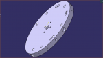
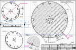
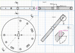
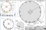
This part is a little bit difficult for me, and I've got many difficulties with the drafting of it. I hope someone could help me, to see if it's clear. This is the part I'm talking about, and the drafting that goes with it.
The upper text in the first drafting page says that two holes of the same size have an angular difference of 90 degrees. Instead of explaining everything, maybe it would be easier if one could just look at it and tell me if it corresponds to the 3D part.

I don't know if there are info's missing, as I'm the one who made it, so it's pretty difficult to look at it from a different perspective.

Thanks a lot in advance !

Stay safe :)
 

Attachments

  • Capture d’écran 2020-06-02 à 13.10.43.png
    Capture d’écran 2020-06-02 à 13.10.43.png
    141.5 KB · Views: 6
  • Capture d’écran 2020-06-02 à 13.11.44.png
    Capture d’écran 2020-06-02 à 13.11.44.png
    463.9 KB · Views: 6
  • Capture d’écran 2020-06-02 à 13.12.08.png
    Capture d’écran 2020-06-02 à 13.12.08.png
    418.1 KB · Views: 5
Just a couple comments:

1. why not use an A1 or A0 paper size to get all the views on one sheet?

2. if the CATIA drawing was generated from the CATIA part, then the drawing matches the part.

3. there are not enough dimensions to locate all the holes. Maybe add a note stating the position of the outside holes is irrelevant to the center mounting holes?

4. there are no dimensions showing how deep the holes are. Might want to dimension the MINIMUM depth.

5. the final drawing check is always "can someone make this part, based on the drawing?"
 
5. the final drawing check is always "can someone make this part, based on the drawing?"

Yes, thanks a lot for your help ! About the drafting, is there everything except the depth of the holes ? Actually, I had put these, but I removed them because I noticed a small mistake. Also, I don't know if you can see, but if I put the depth, how can one know if it starts from the middle part or the lef/right side part ? Maybe take a look at the picture. I added it,

3. there are not enough dimensions to locate all the holes. Maybe add a note stating the position of the outside holes is irrelevant to the center mounting holes?

Sorry, I don't quite understand ? Are you referring to the holes on the side part, and which dimension should I add ? I have a hard time seeing this...
Maybe you could write on my drawing, it was very helpful for the other one :) !

P.S. For the size, you're right, but I was always told that using more than one sheet was never a problem... But next time I'll just listen to you, haha ;) !
 

Attachments

  • Capture d’écran 2020-06-02 à 17.55.37.png
    Capture d’écran 2020-06-02 à 17.55.37.png
    389.1 KB · Views: 1

Articles From 3DCAD World

Sponsor

Back
Top