Hi all,
I'm facing quite a special and difficult task in a startup company.
We are producing 3D extrusion dies where a rotating matrix combined with normal "2D extrusion" can result in extrudede parts with 3D geometry.
However, right now a project is giving me some headache. The geometrical pattern is really complex with a lot of different features, deapths and tight tolerances.
Unfortunetely it's still in a start-up stage so I can reveal so much about it... but I will give it a try:
Imagine you have a pattern in the snow/mud made from a car wheel, but you don't know the pattern on the tire itself.
Someone asks you to CAD-up the tire based on the tracks in the mud/snow.
So you do some kind of reverse engineering from the "flat 3D image" and project it onto the tire itself.. similar to "Wrap" function but the geometry is to complex for that to work with draft angles/fillets/different depths and so on.
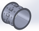
I've tried to bend the track right now using the "Flex" command with 360° to obtain a result. But this process is very unstable and only works with more simplified geometries (e.g. attached)
Results have some surfaces that are transparent/non visible even though SW claims there is a solid body.
Start sketching it onto a cylindrical part from start would take to much time and the risk of me converting 2D sketch manually to a cylndrical face would just make the risk of mistakes to big.
Question 1: Should I continue on this step or do anyone have an idea of another technique / approach for the problem?
Question 2: Is there a way in SW (or any other software) to verify the cylindrical geometry too see if it imprint will give the same result as the original track?
Thanks for the help, and sorry for a bit of a fuzzy description of my problem.


