Join our CAD community forums where over 25,000 users interact to solve day to day problems and share ideas. We encourage you to visit, invite you to participate and look forward to your input and opinions. Acrobat 3D, AutoCAD, Catia, Inventor, IronCAD, Creo, Pro/ENGINEER, Solid Edge, SolidWorks, and others.
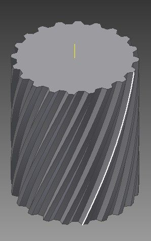
There are many ways to model this gear with CATIA. Often the Generative Shape Design workbench is used to model twisted features. But, here's one way using only the Part Design workbench.
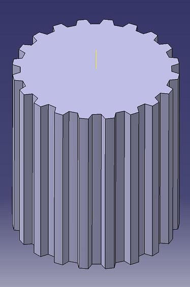
1. Make a sketch of the major diameter of the gear, and PAD this to get the extruded blank.
2. Draw a sketch of one of the gear tooth notches on the top of the blank.
3. Draw another sketch of the gear tooth notch on the bottom of the blank, but with the notch rotated 72° from the other sketch.
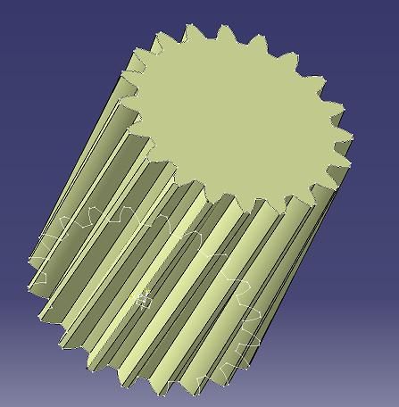
4. Use the REMOVED MULTI-SECTION SOLID command, to model a twisted notch from the top sketch to the bottom sketch.
5. Use CIRCULAR PATTERN to copy the notch based on the number of teeth.
And also now have further understanding of the different ‘workbenches’ available.
I spent a long time trying to complete step one while in ‘sketch’ mode as the ‘Translate’ function is available in this mode but with less functionality and then realised I should be in ‘Generative Shape Design’ mode as you stated above.
I also had a general problem finding the right button to click as there are lots of them and most are hidden in drop down menus. In the end I found it easier to go straight to the customise menu and list all of the commands and then drag the one I wanted to a custom button bar.
Thanks again – this is an excellent forum resource and I’m sure I will be asking more questions in the future.
This site uses cookies to help personalise content, tailor your experience and to keep you logged in if you register.
By continuing to use this site, you are consenting to our use of cookies.