Continue to Site

Welcome to 3DCADForums

Join our CAD community forums where over 25,000 users interact to solve day to day problems and share ideas. We encourage you to visit, invite you to participate and look forward to your input and opinions. Acrobat 3D, AutoCAD, Catia, Inventor, IronCAD, Creo, Pro/ENGINEER, Solid Edge, SolidWorks, and others.

How to "assemble" things in GSD

giangnguyen

New member
Hi everyone,

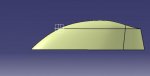
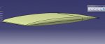
I am a student designing aerodynamics aspect of a car by surface modeling, GSD mode. So far I have drawn separated parts, but I do not know how to connect them together.

These parts are actually airfoil section, formed by connecting coordinates provided, so if I correct their coordinate in order to make them fit together, it is lengthy and tedious.

I have watched some videos of aircraft drawing, but I think it is for illustration purpose rather than exact calculation.

So I attach here my picture and my file for your reference. Let's say if I want to put a canopy on top of the main wing, how can I do that?

https://www.dropbox.com/sh/t1dpttkhv5zitgn/AAA24TsdtmJiwSEMVxDafi5ta?dl=0

Thank you very much for your help.
 

Attachments

  • canopy.jpg
    canopy.jpg
    8.7 KB · Views: 3
  • Main body.jpg
    Main body.jpg
    12.3 KB · Views: 3
CATIA V5 was written to assemble parts and sub-assemblies into a CATProduct with the Assembly Design workbench, which is how users at most companies assemble their parts. Typically parts are designed based on a "master coordinate system" ("airplane coordinate system") which easily locates all the designed parts automatically into position as they are assembled.

Sounds like you have not followed this standard procedure, but you can still insert your parts into an assembly, and then constrain the parts into the necessary position relative to each other.
 
Last edited:
Dear Mr. CATIA,

What I wonder is that I see one of the paper in this area:
https://drive.google.com/file/d/0B2w_1Qf68agHV3MyOUM0emN6aEk/edit

And I see that they drew the whole car in GSD (I see the drawing color, am I right?), and I know exactly is that the author started from the same point as me. It means they designed from scratch, what they have is only airfoil coordinate profiles. Then they build each components, the main wing, the canopy as I. The design is not as fixed as some catia tutor, here they change position of each components for design optimization, for example, moving the canopy backward, forward. But somehow they keep the color of GSD workbench. That is why I wonder how they did that. Did they do that totally in GSD?
 
Based on this additional information, we are not designing all the components of this vehicle, but only doing the aerodynamic analysis of the outside skin. The paper does not state exactly how the model was created, but I'm pretty confident that a simple model such as this was done as a single CATPart file, and not as an assembly. It could have been done as a solid model, but I agree with you that the images in column (b) of Figure 11, page 159, do appear to be surface geometry which most likely was created with CATIA's GSD workbench.

In the original post you asked:

.... if I want to put a canopy on top of the main wing, how can I do that? .......

There are several ways to merge the two models together. I think an easy method is to copy all the geometry from one model and paste it into a new Geometric Set in the other model. (I'm sure there will be some errors that you will have to fix, after pasting.) To position the copied geometry, I would use Transformations to Translate and Rotate the copied geometry in the new Geometric Set.

(If you know how to do a Power Copy, that would be better (no errors) than the Copy and Paste)
 
Last edited:

Articles From 3DCAD World

Sponsor

Back
Top