Continue to Site

Welcome to 3DCADForums

Join our CAD community forums where over 25,000 users interact to solve day to day problems and share ideas. We encourage you to visit, invite you to participate and look forward to your input and opinions. Acrobat 3D, AutoCAD, Catia, Inventor, IronCAD, Creo, Pro/ENGINEER, Solid Edge, SolidWorks, and others.

Another exercise - revolution solid

rbarata

New member
Hello, my friends

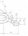
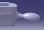
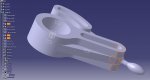
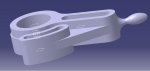
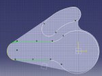
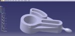
I'm having a lot of doubts about how to create the solid shown in the picture.
I'm not sure about how to sketch it with all those radius. How can I find the center of all of them? I guess that's my main doubt for the moment. Any sugestions?

Thank you
 

Attachments

  • TIP.jpg
    TIP.jpg
    40.9 KB · Views: 20
Good exercise! I suggest you start the sketch with the centerline, and make it an AXIS.

The R8 curve is centered on the end of the centerline. (all the other radii can be added as Corners, so they don't need centerpoints)

The R43 curve is tangent to the R8 curve.

I'm not sure, but the R43 curve might be tangent to the Ø25 point, as I've shown below. If not tangent, the R43 curve passes through the Ø25 point, but that point is not fully dimensioned,

Dimensions are missing for some of the radii. (maybe in the notes or other views ?) Also; missing a couple dimensions to locate the radii.

The R20 radius should not be part of the sketch - it gets added as a Edge Fillet after the Shaft is created.

sketch.JPG
 
Last edited:
This is indeed a very good exercise. It goes a little beyond those simple sketch & part exercises.

I'm still investigating it but, when I create the R20 fillet, I got this error: "Multi-ribbon operator: A single operation can not
process more than one ribbon. Process each ribbon in separate operation.".

What is considered a ribbon in Catia?

Thank you
 
In CATIA, a "ribbon" is a surface. In this case, the ribbons are the faces of the fillet.

My guess is the main body of the part is not thick enough to support a R20 fillet around the Ø12 shaft. Try using a smaller radius for the fillet.
 
I've been doing some exercises with fillets and I think another reason is that I can't use any value for the radius. It depends on the distance between the objects (or faces). For example, I can't apply a R5 mm fillet connecting two bodies that are 50 mm apart. Basically, depending on the distance betwwen both bodies, there is a range of radius values that are geometrically possible to use. This is one of the reasons I could identify. Now I need to understand where are the multi-ribbons and how to solve the error I described.

Thank you.
 
Ok, this exercise is giving me a lot of work.

Now I'm not sure if this was the best strategy but... to build it I've used two sketches.
With sketch 1 I created a "central" pad (pic 1) and on its upper face I created sketch 2, which was used to create a second pad extruded in two directions (pic 2).

The first problem is that the second pad goes through the first. Catia didn't complaint but it doesn't seem the best solution.
Another problem is that both sketches have features in common. So, it creates duplicates.

Anyway, that part was constructed but I can't create a fillet connection the rev solid with the main body. I suspect that those 3 separate surfaces should be connected, since the midle one is not enough for the R20 fillet that should be there.
 

Attachments

  • Pic 2.jpg
    Pic 2.jpg
    102.2 KB · Views: 6
  • Pic 1.jpg
    Pic 1.jpg
    182.4 KB · Views: 10
based on the two attached images, I have two suggestions:

1. instead of including a holes in the first pad, make new sketches of each hole and Pocket them at the bottom of the tree.

2. there's a gap between the main body and the revolution. Extent the revolution so it intersects and ends inside the main body. Then add an Edge Fillet to get the R20 fillet
 
I'm having problems in creating the R20 fillet. As I said in a previous post, the part seems to be divided in three horizontal sections (pic 3) which seems to be the cause of the problems. Everytime the fillet radius goes beyond a certain value, it is formed outside of the central section causing the result shown in pic 4 (as well as a lot of error msgs).

Any sugestions?

Thanks in advance.
 

Attachments

  • Pic 4.jpg
    Pic 4.jpg
    25.4 KB · Views: 3
  • Pic 3.jpg
    Pic 3.jpg
    107.5 KB · Views: 4
My guess is the R20 face is not exactly the same in PAD5, PAD6, and PAD7. Check the sketches and verify the radius is the same value, and the centers are the same also. (This is a good example of defining the R20 circle in one sketch, and then projecting it into the other sketch(s) so everything always matches.)
 
Last edited:
This is a good example of defining the R20 circle in one sketch, and then projecting it into the other sketch(s) so everything always matches.

Yes, that was the root cause. Since some sketches had common features, I used copy & paste but it didn went well (I could confirm it by comparing the circles center point coordinates).

I didn't modify the complete sketches but projected one of the circles (those used to create the pads where the fillet was going to be constructed) on the other sketches and now the result was ok (pic 6). Take a look at pic 5 to see the mismatch between sketches.

Now I will do this exercise again but using the projection feature instead.
 

Attachments

  • Pic 6.jpg
    Pic 6.jpg
    51.9 KB · Views: 2
  • Pic 5.jpg
    Pic 5.jpg
    224.8 KB · Views: 3
Done! In fact, the projection feature, when properly used, makes the job a lot easier and much more simple. The tree has a lot less features than before.

One last question... how can I make the dimension constraints visible in the 3D part view?

Thank you
 

Attachments

  • Pic 7.jpg
    Pic 7.jpg
    86.7 KB · Views: 2
Looks good - good job!

You cannot show the sketch constraints on the 3D part model.

You can add 3D dimensions to the part by using the FT&A workbench.
 
Last edited:

Articles From 3DCAD World

Sponsor

Back
Top