Continue to Site

Welcome to 3DCADForums

Join our CAD community forums where over 25,000 users interact to solve day to day problems and share ideas. We encourage you to visit, invite you to participate and look forward to your input and opinions. Acrobat 3D, AutoCAD, Catia, Inventor, IronCAD, Creo, Pro/ENGINEER, Solid Edge, SolidWorks, and others.

Cables

spider007

New member
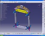
I should probalby start thinking about how to put the cables in (wires from corner to corner). They will all be different size, and this being a bi-plane, THERE IS TONS OF THEM.

As of right now i'm thinking of drawing one, saving it, masure the distance between bracktes (blue brackets in pic,), go back and make it that long, then add it to the assambly. Looks like a retarded way of doing it (especially since i got like 50 cables)

IS THERE A BETTER WAY?:confused:
 

Attachments

  • CABLES.JPG
    CABLES.JPG
    173.2 KB · Views: 19
I guess the method depends on how accurately you want to represent the cables.

Is just a line good enough? Or do you want to show the cable gauge? What about the end connectors?

I'd suggest making a single CATPart in your assembly for all the wires. And then just make Point-Point lines between the connecting centers of the other parts. (this will make external reference links to the other parts)

If you want to show more than the lines, then use a RIB feature.

If you want the connectors, then PowerCopy would be the quick and dirty way to duplicate them. Or setup a catalog.
 

Articles From 3DCAD World

Sponsor

Back
Top