Continue to Site

Welcome to 3DCADForums

Join our CAD community forums where over 25,000 users interact to solve day to day problems and share ideas. We encourage you to visit, invite you to participate and look forward to your input and opinions. Acrobat 3D, AutoCAD, Catia, Inventor, IronCAD, Creo, Pro/ENGINEER, Solid Edge, SolidWorks, and others.

Flip object in CATIA

bhavasser

New member
Hi!

I just stumbled upon these forums when I started learning CATIA last month and have learned a lot from this site. I had a question to ask other designers:

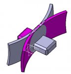
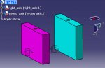
How do I flip a model around in CATIA so that it flips one of my axes? I have attached an example model where I want it to point in the positive Z-direction while keeping the point of origin intact. I have tried using mirror tool but I cannot do that in assembly mode. Any help on this would be appreciated.

Thank You
 

Attachments

  • radar_scanner.zip
    60.1 KB · Views: 50
Like the picture below?

Insert the part into a Product, and then use the Symmetry tool to make a new, left-handed part. I flipped the part around the XY plane.

The new part is copied from the original, with a link. So if the original part is changed, the flipped part will change also.

Another option: I notice that your part is symmetrical to begin with, so you really don't need to flip it. Just copy the instance in the Product, and then contrain it to rotate it into it's "symmetrical" position.
 

Attachments

  • symmetry.jpg
    symmetry.jpg
    22.2 KB · Views: 8
Last edited:
Thanks for your help MrCATIA!

I can rotate the part now but how do I rotate an assembly? I am sorry I will not be able to upload the assembly as I am under a NDA but the previous designer fixed an axis at the the wrong edge of a cube and now the y-axis is pointing in the opposite direction. How do I change the point of origin and the direction of y-axis without recreating the geometry?

Thanks for your earlier reply again!
 
I was a little confused by the original question, so my first reply was a little off-base.

I'm still not totally sure I understand what you want to do, but I'll try again:

The way your part was defined makes it very difficult to reposition the geometry in a different orientation. It could be done with Transformations, but they only makes editing the original geometry more confusing.

I suggest adding a new Axis System at the requred point and direction. You can easily do this with the top menu bar: INSERT + AXIS SYSTEM

Let me know if I'm still not answering your question
 
Last edited:
Another comment about orienting parts:

Generally, it doesn't matter how the part is oriented and positioned about the part's Axis (coordinate system). When the part is used in an assembly, it can be positioned relative to the other parts with Assembly Constraints.
 
Thanks a lot for the reply MrCATIA. Sorry about being vague about the problem description. I want to rotate my assembly 180 degrees through its midplane so that it is pointing in the opposite direction. I have attached two simplified reps of my assembly showing what I want to do with my model (change from wrong axis to right axis). Thank you for the other help though!
 

Attachments

  • simplireps.zip
    53.6 KB · Views: 5
bhavasser,

I don't see anything wrong with with the Wrong Axis part. The hole is in the +Z direction (instead of the -Z direction), but so what? Looks like the part is modeled correctly to define the exact size and shape of what you're trying to define.

As my picture below shows, you can take the wrong part and rotate it in the assembly into the correct orientation. (purple is right, blue is wrong, both holes are in -z direction)

Is there any specific reason why you want the part built in that particular orientation?
 

Attachments

  • flipaxis.jpg
    flipaxis.jpg
    33.1 KB · Views: 4
I am in the CFD industry and CFD software is very specific about the orientation of axes on a model. Modelling a vertical flow with gravity makes the orientation of any details very important and even small mistakes like these can waste many man-hours. Thank you for the reply!
 
Thanks for explaining why the part orientation is important. I can suggest 3 ways to reorient the part around the axis system.

1. The easiest way is to create a new Axis System, and use that for your CFD analysis,

or

2. Use Transformations (Axis-Axis, Translate, Rotate) to reorient the part to the Absolute Axis System. (for your part, Rotate the PartBody 180° about the X-axis)
or

3. Start with a new Part file and rebuild the geometry in the correct orientation.
 

Articles From 3DCAD World

Sponsor

Back
Top