GabrieleJax
New member
Hi everyone,
I'm new to SolidWorks Flow Simulation and I have to simulate the air flow through an enclosure with electronic components in it.
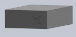
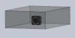
My model is the one shown in figures a.jpg and b.jpg attached to this post (At the moment I've only modelled the openings through which air enters the enclosure and the fan that lets air in).
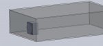
To analyze this model I would create the simplified model shown in figure c.jpg and then I would apply the following conditions:
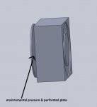
- on the inner surface of the lid (that is necessary to perform an internal analysis), I would apply environmental pressure boundary condition and then perforated plate condition (because in the real model there are lots of small vents (figure d.jpg)
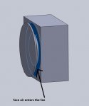
- then I would model the fan as an internal fan and consider the surface in front of the lid as the face through which air enters the fan (e.jpg) and the opposite surfaces as the face air exits the fan
Do you think this is a good way of solving this problem? Or should I treat the fan as an external inlet fan (because, although the fan is inside the enclosure, it lets air in)?
Thanks
I'm new to SolidWorks Flow Simulation and I have to simulate the air flow through an enclosure with electronic components in it.
My model is the one shown in figures a.jpg and b.jpg attached to this post (At the moment I've only modelled the openings through which air enters the enclosure and the fan that lets air in).
To analyze this model I would create the simplified model shown in figure c.jpg and then I would apply the following conditions:
- on the inner surface of the lid (that is necessary to perform an internal analysis), I would apply environmental pressure boundary condition and then perforated plate condition (because in the real model there are lots of small vents (figure d.jpg)
- then I would model the fan as an internal fan and consider the surface in front of the lid as the face through which air enters the fan (e.jpg) and the opposite surfaces as the face air exits the fan
Do you think this is a good way of solving this problem? Or should I treat the fan as an external inlet fan (because, although the fan is inside the enclosure, it lets air in)?
Thanks