Continue to Site

Welcome to 3DCADForums

Join our CAD community forums where over 25,000 users interact to solve day to day problems and share ideas. We encourage you to visit, invite you to participate and look forward to your input and opinions. Acrobat 3D, AutoCAD, Catia, Inventor, IronCAD, Creo, Pro/ENGINEER, Solid Edge, SolidWorks, and others.

Generating Aerofoils / Wings

Lost1e

Newbie
Please help; I am a 3rd year engineering student starting my final project. I am looking at the effects of induced drag over an aerofoil. This is my problem starts; I have been using creo elements for the past 2 years now all programs I need to use requires catia CAD models (using v5r21). I have never used catia before and I am currently trying to self-study the tutorials and learn myself.

What I have already worked out myself.
I have gotten aerofoil co-ordinates from a website generator
Generated aerofoil with “GSD_PointSplineLoftFromExcel”

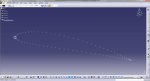
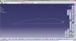
Problem 1 – using GSD_PointSplineLoftFromExcel – points macro
Using just points – not able to link points with any drawing line to produce initial aerofoil shape; therefore not able to extrude into basic wing shape. (Picture 1)

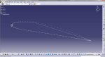
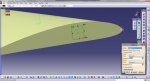
Problem 2 – using GSD_PointSplineLoftFromExcel – spline macro
Using spline option, - spline lines do not go from point to point, Picture 2 shows what I am on about.

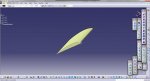
Once I have done this then I make the basic wing shape then create wing tip aerofoils and attach to the basic wing.
Am I doing this right or does anybody know a better way to do this.

Thank you for your help and reading this.
 

Attachments

  • points.jpg
    points.jpg
    154.8 KB · Views: 24
  • spline.jpg
    spline.jpg
    165.8 KB · Views: 24
You are using the macro all wrong.

When you run the macro, you have 4 to choose from. The first 3 in the list are just references for the main macro. Run the "main" macro which is at the bottom of the list. This gives you a dialogue box where it runs only points, only points & splines and only Points, splines and lofts. You are interested in "option 2".

I have done many aerofoils this way without issues. I have had to tidy the geometry up in some instances but needless to say, the spline did go through every point. Let me know how you get on.
 
Hi there, you are using the macro wrong. It appears you are running the "reference" macro's.

As you have managed to plot the points, it appears the format of your spreadsheet is correct.

When you run the macro, you should see 4 macro's; 1) Points 2) Splines 3) Lofts 4) main.

You want to run the "Main" macro. This macro refers to macros 1)-3).

When you run the "Main" macro, you will be given options to:

enter 1 for points
enter 2 for points and splines (spline passes through each point)
enter 3 for points splines and lofts (must be minimum of two diff splines, defined by "end curve" in the spreadsheet).

You are interested in entering "2". I have done exactly what you are after with no issues so works flawlessly. However Id id have to tidy the geometry a little towards the TE and LE but lets see what you think of the end result.

Hope this helps.
 
Hi Thanks for your help,

I understand about the macro, I watched the YouTube demo and understood what to do; (regarding the macro).

My problem comes with the produced spline line not picking up all points, therefor not producing a correct aerofoil profile. (attached picture)

What I want it to do is; the spline line to pick up all points producing a correct aerofoil profile. or easily edit the spline line to pick up the missed points.

As you said it needs tidying up, this is what I don't know how to do !!
(attached picture shows spline line NOT picking up all points, when I need it to pick up ALL points)


This will then produce a true 2d representation, then I can extrude the 2d shape into a 3d wing. then I can add the different wing tips.
 

Attachments

  • spline.jpg
    spline.jpg
    165.8 KB · Views: 13
Lost1e,

As a last resort, you can edit the Spline curve (double-click on it) and add (or remove) points to the spline's definition. Be careful to get all the points in the correct sequence.

This is a lot of work, selecting all the points; I would double-check the spreadsheet first to try to find out why the macro doesn't produce the correct spline.
 
Hi
I have figured it out; it was all to do with the points. Andthe accuracy of the spline, well I didn’t some body on YouTube did.
The fix:
1. Go to: tools -> options ->performance
2. Under 3Daccuracy, change proportional to 0.01
3. Click ok

Now that makes the spline gothrough each point.

Next questions,

1) I havefilled the spline then extruded it; I am trying to round one end of theextrusion, but for some reason it won’t let me – how do I make one of the wing endsrounded? (Radius the wing end to extrusion)

2) These wingsare going too manufactured and tested in a wind tunnel; I need to fit them on asquare rod. I have made the rod shape on one wing end and extruded it into thewing but it does not cut away the square shape. How do I make the square holefor the rod?

3) Once this isdone I am going to fit the Airbus end onto the rounded wing end and smooth outthe transition, how do I do this? Also on the airbus end how do I round theextrusion edges to faces to make it more aerodynamic? (Radius the end toextrusion)

Thanks for your help.
 

Attachments

  • 3D Accuracy.jpg
    3D Accuracy.jpg
    32 KB · Views: 16
  • Extrude.jpg
    Extrude.jpg
    19.6 KB · Views: 11
  • Spline Points.jpg
    Spline Points.jpg
    19 KB · Views: 11
  • Fixture Hole.jpg
    Fixture Hole.jpg
    22.7 KB · Views: 15
  • Airbus End.jpg
    Airbus End.jpg
    19.4 KB · Views: 14
1) I havefilled the spline then extruded it; I am trying to round one end of theextrusion, but for some reason it won’t let me – how do I make one of the wing endsrounded? (Radius the wing end to extrusion)

I see from the attached pictures that you've defined the airfoil as a surface with the Generative Shape Design workbench. For your project, I suggest:

1. switch to the Part Design workbench (solid modeling)
2. use the Close Surface command to convert the surface into a solid.

then, just use the Edge Fillet tool to roundoff the end of the wing.

Or, stay in the Generative Shape Design workbench and build some surfaces that define the wing tip. (Aerospace Lofters can spend days or weeks on this, so I'm not going to get into the details.)
 
Last edited:
2) These wingsare going too manufactured and tested in a wind tunnel; I need to fit them on asquare rod. I have made the rod shape on one wing end and extruded it into thewing but it does not cut away the square shape. How do I make the square holefor the rod?

Once you've converted the airfoil into a solid, extrude the shape (sketch) with the Pocket command to make a hole.
 
Last edited:
3) Once this is done I am going to fit the Airbus end onto the rounded wing end and smooth out the transition, how do I do this?


Looks like the Airbus wingtip is already a solid. So just "copy & paste"

1. with the wingtip model open and the tree expanded, right-click on the PartBody and COPY
2. change windows to your airfoil model
3. right-click on the top of the tree and PASTE (this will make a new body, probably at the bottom of the tree)
4. use the TRANSFORMATION tools (TRANSLATE and/or ROTATE) to position the wingtip body
5. use the BOOLEAN OPERATION + ADD tool to add the wingtip Body to the airfoil

Hopefully, the fillet tools in Part Design will allow you to smooth out the transistion area. The Multi-Section Solid tool might be useful also. (in the real-world, the Lofter would use the surface tools to define a smooth transistion shape)
 
Last edited:

Articles From 3DCAD World

Sponsor

Back
Top