Continue to Site

Welcome to 3DCADForums

Join our CAD community forums where over 25,000 users interact to solve day to day problems and share ideas. We encourage you to visit, invite you to participate and look forward to your input and opinions. Acrobat 3D, AutoCAD, Catia, Inventor, IronCAD, Creo, Pro/ENGINEER, Solid Edge, SolidWorks, and others.

how to run a profile along a curve

K

knabini

Guest
and gradually change it to a different profile. I'm trying to do this on CAD 2006 and, so far, no luck. I'd really appreciate your help.
 
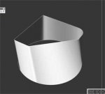
To the best of my knowledge all you can do is fudge it up in solids however you can do it using surfaces. The "rulesurf" command will make a mesh from one polyline to the other as long as they are not closed (see attached pic). Be sure to set your "surftab1" & "surftab2" to a high resolution say around 64 depending on the detail you want. In addition to a high surftab you might also have to drag some grips around once you have made your mesh so it meets the corners properly.

But it just seems to easy doesn't it? you can't project profiles using "SOLPROF" of a mesh as it won't recognise it. But for a shaded 3D view it will solve your drama's and I'm sure you will be able to fudge something up for the 2D views.

Hope this helps mate,
Stewy C. :)

rulesurf.jpg
 
Changing Profile On A Curve

Hello Knabini,

Try EDGESURF.
This is another wireframing method. Not solid.
( other methods are revsurf, tabsurf & rulesurf )
I daresay you will probably know most or all of what I am about to say, but for anyone else who is interested please read on. Thank you.
You will need to alter two system variables called Surftab1 & Surftab2 whose initial values are by default, 6 each. These are the mesh densities & should be increased to say 24 or more depending on the size and length to width ratios. These two variables don’t have to be equal. If your object is say four times longer than it is wide, then one of the settings could be four times greater, especially when long curves are involved. Each object you make can have it’s own preset surftab values.
Surftab1 is the ‘m’ value whilst Surftab2 is the ‘n’ value.
Each meshed object uses 4 sides as the boundary by which it is made. 4 entities. Each entity can be a line or a polyline or an arc. The ends of each entity side must touch at the corners.

Once the mesh is made you then need to use the 3D Mirror command.

Whichever side you pick first will be the Surftab1 setting. AutoCAD is then able to work out which ones will be allocated the Surftab2 value. All in the blink of an eye.
As you know doubt are aware there are NO TRUE CURVES in AutoCAD. It only looks that way. All circles & arcs are made up of straight line segments. Every so often you need to carry out a Regen.
The mesh is made up of FACETS. Lots of them!
The more there is, the smoother it looks. The more there is, the more ‘grunt’ your computer will need.

Other system variables which will be of use to you before, during & after this process are Facetres, Isolines & Viewres. Look up the ‘Help’ files to see their definitions.

However, surprisingly, the Dispsilh setvar does’nt seem to work with meshes for a printout ! ! Eh??
Why not?

They say a picture speaks a thousand words, so please, take a look at my diagrames attached. Hopefully these will depict AutoCADs capabilities satisfactorily.
I have set both surftabs in my diagrames on the low side purely for clarity but as Stewyc suggests, bump them up to 36 or higher for a real smooth job!
The picture file is a bitmap (.bmp) inserted into an MSWord’97 document, on an A4 sheet & it's zipped.

I hope this has been usefull. If so, throw me a thread.

Regards

Stephen
 

Attachments

  • EDGESURF DIAGRAMES.zip
    172.8 KB · Views: 18

Articles From 3DCAD World

Sponsor

Back
Top