Continue to Site
Follow along with the video below to see how to install our site as a web app on your home screen.

Note: this_feature_currently_requires_accessing_site_using_safari
Is it possible for you to post the file or more info regarding the profiles and their respective positions as its a bit difficult to tell whats really going on.?
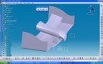
") it's smarter to mirror the whole part, becouse it's symetric, and it's easier... I am now still working the ''nose'' abit of desinging mistakes i made, and I correct them now... I have also desingned a wheel, here is the picture... post your comments...
it's smarter to mirror the whole part, becouse it's symetric, and it's easier... I am now still working the ''nose'' abit of desinging mistakes i made, and I correct them now... I have also desingned a wheel, here is the picture... post your comments...