Continue to Site

Welcome to 3DCADForums

Join our CAD community forums where over 25,000 users interact to solve day to day problems and share ideas. We encourage you to visit, invite you to participate and look forward to your input and opinions. Acrobat 3D, AutoCAD, Catia, Inventor, IronCAD, Creo, Pro/ENGINEER, Solid Edge, SolidWorks, and others.

new project....help me along

spider007

New member
HI

First of all, my experiance with catia is 3 semmesters at school (30 or so days) so forgive me if my questions seem simple.

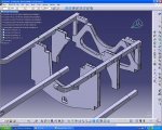
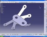
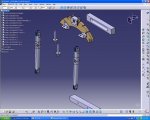
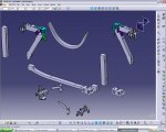
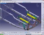
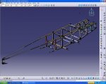
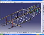
I'm starting a new project in the next couple of days (a print to cad of an WW1 airplane or an local non profit organization) and i had couple of quiestions, one of which is as follows;

-There will be a lot of parts for this project (2 000 or so), so my main concern is the links in the assambly. if at the end i copy the main folder from computer to cd to computer will it break the links?

I'll post an update in the next few days showing my progress....;)
 
Sounds like a good project for school, as well as for the local organization.

As long as you use FILE+SAVE MANGEMENT whenever you copy or SAVE AS, then the links should be remain good. If you just copy the folder, the links probably will be broken!

Publishing your parent geometry and only using published geometry to create links will help tremendously if the links do become broken.

If you have 2000 parts, I also suggest organizing the data into several sub-products.
 
good idea.

I guess the second question would be this;

I got a L/H, part with bunch of solids in it (a longeron, with shims) how do i mirror it into a R/H part. I seem to be having trouble with it because the solids are referenced to each other.

I was planing on mirroring them and saving the file as R/H...

From what i understand i Should be doing one solid per part but these shims don't have part numbers and arn't very important, so i figure i trow it together.
 

Attachments

  • 1.JPG
    1.JPG
    133.2 KB · Views: 31
In real life, all the shims are actual parts with partnumbers that should be modeled as separate CATPart files. A sub-assembly should be made of the longeron and all the shims. And the RH version of the sub-assembly can be made my using the Symmetry tool in the Assembly Design workbench (where you would define which parts are actually mirrored, and which parts can be re-instanced by rotating or translating them). This is what real Engineers/Designers do when designing a real airplane with CATIA.

But.... you are a student doing a quick little project just for fun and without having to worry about things like manufacturing and BOMs and revisions, so you can take some shortcuts.;) Based on your attachment, I would boolean assemble all the shims into the longeron so you endup with a single partbody of the LH assembly. I would publish the partbody, and then copy and paste special with link the partbody into a brand new CATPart, and then apply a symmetry to make a RH assembly. (if you modify the LH assembly, the RH changes also). :cool:
 
spider007

What plane is it? Do you have actual production drawings?Do you need help with the modelling? I would be very glad to help out if you require. Would just love to model an actual plane in Catia...
 
we have prints that we bought off the internat from a guy that is also into this stuff....he did all required reserch and made condenced set of prints (about 9 pages). The thing is, they want to use cad files to cut the wood stuff on their rouder, waterjet all the brackets (of which there is a lot), and basicly work out all the bugs before they start building it

The plane is SE5a scout, from WW1, seen in this picture below

I'd love to have some help, but this is volonteer work, and on top of that i only have hard copy drawings, which isn't exacly ideal for over internet work.
It isn't as fun as you may think, most of the time is spent trying to read the drawings, just because the guy who drew the set condenced is so much.....it takes a lot of time....time i could be spending drinking beer and chasing women....

If you are still looking for a project like that go on http://www.replicraft.us.fm/pricelist.html and for 120 you could get a set you can do your self. Better yat, find a fun plane with no drawings out there...and do some reserch in the archives, and draw one from original production drawings...

HELP SAVE OUR HISTORY

The collage is donating the machinery time, and computer/sofware time, and the organization is providing the materials, and the skill (or lack of it, in my case) I told them, my time would be better spent running the CNC :D

i'll keep this forum updated (and maybe another forum) just to get some feed back from experienced people

Mr Catia; I'll do the modeling as "profesional" as i can.....I'd hate to cause a heart attack to the guy that opens this file 10 years from now, when he wants to build one too.
 

Attachments

  • SE5aOne.jpg
    SE5aOne.jpg
    277 KB · Views: 20
I'd love to have some help, but this is volonteer work, and on top of that i only have hard copy drawings,QUOTE]

I gathered that it might be volunteer work and its a pity that all you have are hard copy drawings as the offer to help still stands.I love anything to do with aviation. and am also learning catia...Cant think of a better way to learn than such a project as you have ....Anyway let us know of your progress often and feel free to shout if you hit a hurdle or 2 along the way...

[email protected]
 
I have a feeling this will get complicated soon enough.

there are brackets that join all the struts....i haven't done them yat....

i'll work on it a bit more on the weekend
 

Attachments

  • STATION 2.JPG
    STATION 2.JPG
    122.6 KB · Views: 29
  • ASSEMBLY.JPG
    ASSEMBLY.JPG
    167.9 KB · Views: 33
tree zooming

I avoid the problem by using a 3-button mouse that doesn't have a wheel.

You can also avoid the problem with your settings: Tools + Options + General + Display and in the Tree Manipulation tab: turn OFF the ZOOM ON TREE option (Tree zoom after clicking on any branch). To zoom the tree after you turned off this setting, select the axis in the lower-right corner to activate the tree, zoom the tree, and select the axis again to de-active the tree.
 
yes that fixed the zoom, but my problem was scrolling.....I'll see tonight if I can steal a better mouse from another room.

93 files completed so far. This is turning into an assambly nightmare. I'll post a picture maybe at the end of the week when i get most of that together.....

So far, i have only one part that i have a problem modeling.....it's a 3/4 id tube that was squished on one end down to .306 inbetween wals. The tube was sloted inbetween the squished walls and a u shaped piece was inserted in and welded. I tried modeling it using multi section solid, but it just didn't look right. I'll see if i can scan the part of the print later tonight and post it on here.
 

Attachments

  • untitled.JPG
    untitled.JPG
    16.9 KB · Views: 15
Last edited:
Spider....

To make it easier for other readers, please create a new thread for the squished tube problem and any other new topics that come up.

Let's continue on with this thread to keep up with your progress on the SE5A Scout project. It's looking good so far, and many of us (myself included) are anxious to follow your progress with it.
 
no problem.... i guess it would be kinda nice having a record of the whole progres (especialy with the project this big)

well here is the update.....not a whole lot done in the few days that passed since i started this.....

so far, about 95 CATparts in my folder.

getting it assambled, that's another storry:eek: My goal is; by monday, have it somewhat recognizable (most of the fuselage main parts assambled into it's proper position)

I played around a little bit with the sheet metal workbench.....i started off not liking it very much....but the more i used it the better it got.

i had 7 brackets that look like the one below, with catia it was easy, change the angle and save it...;)
 

Attachments

  • front.JPG
    front.JPG
    200.3 KB · Views: 17
  • BRACKET.JPG
    BRACKET.JPG
    134.6 KB · Views: 16
  • station 12.JPG
    station 12.JPG
    152.3 KB · Views: 18
Last edited:
Don't use save as that th e wrong way

The correct way to save your product making sure all yours parts follow on to the cd/dvd or what ever is first to file/save all then file/send to.
 
good to know david.

well, i've put in about 10 hours last week......soo many brackets.....started assembling them in yesturday....lots of fun.....

I don't really have much to show-off, because i do this in my spare time (when i have some), and a lot of time is spent reading the prints and trying to figure out what goes where and how...

this is gona take a lot longer then i thought it would, and it'll be bigger pain in the side then i thought it would.....
 

Attachments

  • UPDATE.JPG
    UPDATE.JPG
    147.8 KB · Views: 17
Update

Not fully constrained.....I'm starting to find out that the drawing don't match what i'm getting in cad....And from what the guy that is builidng it is telling me, it was all compiled from different sources and it had to be matched to the plane. So now i'm tweeking (sp?) things.

STILL NOT FULLY CONSTRAIND.
 

Attachments

  • latest.JPG
    latest.JPG
    265.8 KB · Views: 18
i know i've been showing this front end a few times, but i had to rework it few times too:D

208 files so far.

my girll has been complaining.:rolleyes: too much time on the computer....
 

Attachments

  • 208 files total.JPG
    208 files total.JPG
    153.3 KB · Views: 15
  • 2.JPG
    2.JPG
    144.8 KB · Views: 11
  • 1.JPG
    1.JPG
    290.7 KB · Views: 15
geezz, i thought i'd be done this by now....i'm just 1/4 of the way...
 

Attachments

  • so far.JPG
    so far.JPG
    154.9 KB · Views: 10
  • so far2.JPG
    so far2.JPG
    216.6 KB · Views: 7

Articles From 3DCAD World

Sponsor

Back
Top