Continue to Site

Welcome to 3DCADForums

Join our CAD community forums where over 25,000 users interact to solve day to day problems and share ideas. We encourage you to visit, invite you to participate and look forward to your input and opinions. Acrobat 3D, AutoCAD, Catia, Inventor, IronCAD, Creo, Pro/ENGINEER, Solid Edge, SolidWorks, and others.

Pattern or Any Ways to do thing?

Alvin Winly Low

New member
Is there a way to fill a surface of certain shape with multiple holes where the holes is always located inside my shape boundary?
instead of manually making each holes? something like the bottom image where the pattern of the holes is always limited by the shape boundary

6a00e553fcbfc68834017d4262bede970c-pi
 
There are two ways to do this, but it might be easiest to use a combination of both methods:

1. When you make the the Pattern, select the orange dots where you don't the hole to be duplicated

2. Make the Pattern so it overlaps the boundary, then add a Pocket the removes all the holes outside of the boundary

If you use both methods; use #1 to remove the holes that are split by the boundary, and use #2 to remove the holes outside of the boundary.
 
Last edited:
ill try it and see
but is there a way where the holes is be bounded to the boundary by a certain formula or relation? because the shape and size of the boundary is a parameter where it can be changed.... when the parameter is changed, the shape / size of boundary will varies and so should the hole always remain in it

really appreciate all the support and suggections
 
i did a simple drawing in paint to illustrate my problem :
Untitled.jpg
the tiny blue circle represent the holes that are needed to fill up the empty spaces which should not overlap with the other boundary (in black) yet the position of them can be varies
 
Maybe this can be done with a macro or program? Especially if the boundary and hole positions can change.
 
i see.... i have no experience of writing macro for catia so i would like to avoid that method if its possible.. but if you do have a guide about macro for defining pattern...it would be great as well
 
Alvin: do the holes always have to be whole? Is it OK if some of the holes are partial circles?

Also, can the holes break through the boundary? Does there have to be a minimum amount of material at the boundary?
 
the holes should be whole but it should not be a problem if its partial as the material will be 3d printed as long as it remain within the boundary

i dont understand what do u mean about the second question... it;s generally a sheet of round material with 2 big holes-input n output holes (where the position and size can varies)..the small holes which is the perforation must of course be inside the materials and not intersect with the 2 big holes
 
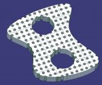
If partial holes are OK, this might be easy to accomplish. But you can see the holes break through the boundary.
holes1.JPG

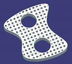
So here I've added a minimum distance of material, so that the boundaries are not broken.
holes2.JPG

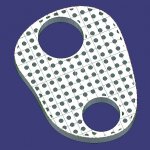
And the hole pattern adjusts as the boundary shape is modified
holes3.JPG

Is this what you're looking for?
 
Sure, the original problem can be done with a flat surface. Just use Split to remove the boundary shape and the hole pattern.
surf holes.JPG

Or, you could just Extract a surface from the solid model.

I'm not sure how you would 3D print this surface?
 
Last edited:
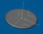
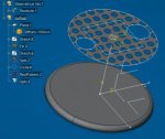
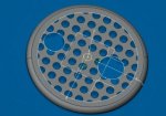
ya..i thought of that method.. it can worked but i need to somehow merge/intersect/paste that surface onto a plate (made through revolution) :
Capture.jpg.. so that the plate will have that particular pattern design....
is there a correct method to do it? because i keep having error when i try using join.... maybe because its overlapping surface....
 
Capture.jpg

i have something like this.... so if i can somehow make the surface merge onto the plate... then the problem should be solved.... but i dont know the right way to do it... or what is the right method to do it
 
1.jpg
realise i made some mistake in splitting.... but somehow manage to solve the problem now..thank a lot for your guidance...
now i willl work on constructing the right boundary shape to fit my problem... thank you again for the help given
 
sorry for the trouble... i think this method cant work in surface modelling :(

ya..i thought of that method.. it can worked but i need to somehow merge/intersect/paste that surface onto a plate (made through revolution) :
View attachment 1755.. so that the plate will have that particular pattern design....
is there a correct method to do it? because i keep having error when i try using join.... maybe because its overlapping surface....

The part above can easily be modeled with solids in the Part Design workbench, without using surfaces. Solids is the most correct method (with or without Booleans).
 
Last edited:

Articles From 3DCAD World

Sponsor

Back
Top