Continue to Site

Welcome to 3DCADForums

Join our CAD community forums where over 25,000 users interact to solve day to day problems and share ideas. We encourage you to visit, invite you to participate and look forward to your input and opinions. Acrobat 3D, AutoCAD, Catia, Inventor, IronCAD, Creo, Pro/ENGINEER, Solid Edge, SolidWorks, and others.

Problems with Corners

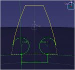
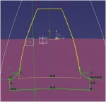
I am currently creating a fully parametric Bevel Gear on Catia but, naturally, I'm having a few problems when it comes to fine tuning the part. When I have the gear tooth number under 40 the corners that I have created are fine but when it goes over this number the corners flip and therefore it doesn't work. I am just wondering whether anyone knows how best to constrain the corners so they don't do this. Whatever I have tried so far, the corners just become over constrained.

I will add some screen shots so you can see what I mean

Any help would be much appreciated.

Thanks
 

Attachments

  • Over 40.JPG
    Over 40.JPG
    41.4 KB · Views: 7
  • Under40.JPG
    Under40.JPG
    38 KB · Views: 5
One solution is to not include the corners in the tooth profile sketch, but add them as Edge Fillets after the Pad feature.

I like using a tree structure that I've attached below, with corners added where the teeth intersect the hub. It's very robust and works well with parameteric models.
 

Attachments

  • FILLET.JPG
    FILLET.JPG
    55.3 KB · Views: 6
Last edited:

Articles From 3DCAD World

Sponsor

Back
Top