Continue to Site

Welcome to 3DCADForums

Join our CAD community forums where over 25,000 users interact to solve day to day problems and share ideas. We encourage you to visit, invite you to participate and look forward to your input and opinions. Acrobat 3D, AutoCAD, Catia, Inventor, IronCAD, Creo, Pro/ENGINEER, Solid Edge, SolidWorks, and others.

Screw inserting in assembly

marcofa

New member
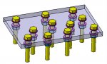
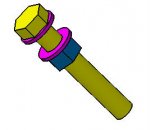
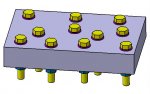
To draw in Autocad many screw and bolt in an assembly I created a components ( Bolt + washer + washer + nut ) database to copy and paste . Different composition i.e. distance from bolt head and nut 10, 15, 20, 25, 30 mm was designed and stored.
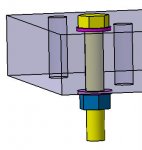
In Catia v5 to insert in an assembly many bolts with washer and nut is very hard: bolt constrains + washer constrains + washer constrains + nut constrains.

There is a clever system to save time and energy?
Marco
 
A couple things that might help:

1. Make an Assembly to Copy

Make a little assembly of all the fastner parts and constrain as much of the parts as possible. Then copy & paste all the fastner parts into your real assembly and just add the two or three constraints to locate the final position.

Make sure you go to Tools + Options + Mechanical Design + Assembly Design, and turn on the ALWAYS WITH ASSEMBLY CONTRAINTS option to paste the constraints with the fastner parts.

2. Using Publications would help also.

3. ReUse Pattern

The ReUse Pattern tool will duplicate the fastner parts if a pattern was previously used to define all the holes for the fastners.
 
Thanks for thr answer.
Some comments:
1. This is the system I use in Autocad.
This system in Catia avoid the possibilities to modify the thickness of the two fastened parts. Distance from bolt head and nut will not be updated.
No others system to solve this??

3.Seems that I can reuse the same pattern used to define holes?
Marco
 
Marcofa,

1. After you copy all the parts, add a constraint to position the bolt head and add another constraint to position the nut. These constraints will keep the bolt and nut in correct position with different widths.

If you are using parameters to specify the head-to-nut distance, you might be able to use the same parameter to drive an Offset constraint.

3. Yes! If the holes change, the fastner parts change also
 
1. not clear for me.
"After you copy all the part" : What part ?
"constaint the bolt" 2 constraint , "constraint the nut" 2 constraint ; total 4 constraint for each bolt, and whasers?
Can you write simple step by step exemple from the beginning pls?

2. I create a Bolt subassembly (bolt+washer+washer+nut) with all constraint and parameter between bolt head and nut.
What parameter I use? There is not defined relations with others parts.

After inserting in my Bigassembly how can I link the parameter to the sum of the two connected thicknesses?
Can you again write simple step by step exemple from the beginning pls?

Thanks
Marco
 
Marco, I see you are getting alot of advice in various CATIA forums. Most people seem to agree that REUSE PATTERN will do what you described. There's alot of good advice (and some not so good), so I hope you are able to find the best solution for you.

(I'm using attachment 1 below for reference)

Here's the steps I recommend. Someone suggested using a Component Assembly and I think it's a better idea than what I first suggested.

1. Make the Big Assembly consisting of the plates with holes

2. Add a Component Assembly containing the fastener parts (bolt, washers (2), nut - see attachment 2)

3. In the Component Assembly, Coincidence constrain the washers and nut to be co-axial to the bolt. Contact constrain one washer to the bolt head, and Contact Constrain the other washer to the nut face. (do not FIX the bolt). These constraints will be the same on every set of fastners, and only have to be added once!

4. Make the Component Assembly a FLEXIBLE/RIGID SUB-ASSEMBLY. This will allow you to vary the distance between washers!

5. In the Big Assembly, Contact constrain the washer faces to the top and bottom faces of the hole plate. (If you vary the width of the plate, the fastner parts should move accordingly - see attachment 3)

6. In the Big Assembly, use REUSE PATTERN to copy and position the Component Assembly based on the same pattern that was used to add the holes to the plate. (see attachment 4)

When you are done, your tree should look something like attachment 5
 

Attachments

  • reuse pat 1.jpg
    reuse pat 1.jpg
    55.9 KB · Views: 10
  • reuse pat 2.jpg
    reuse pat 2.jpg
    10.3 KB · Views: 5
  • reuse pat 3.jpg
    reuse pat 3.jpg
    17.2 KB · Views: 5
  • reuse pat 4.jpg
    reuse pat 4.jpg
    34 KB · Views: 4
  • reuse pat 5.jpg
    reuse pat 5.jpg
    91.2 KB · Views: 11
Last edited:
Thanks Mr Catia BINGO!!!!!!
This is the best way to do the job.

I tryed but I found problem.
After inserting components assembly in the big assembly, I make components assembly flexible. After applying the command NUT DISAPPEAR.
I dont know what appens !!

Enclosed file
Marco
 

Attachments

  • Exemple.zip
    211.7 KB · Views: 30

Articles From 3DCAD World

Sponsor

Back
Top