Continue to Site

Welcome to 3DCADForums

Join our CAD community forums where over 25,000 users interact to solve day to day problems and share ideas. We encourage you to visit, invite you to participate and look forward to your input and opinions. Acrobat 3D, AutoCAD, Catia, Inventor, IronCAD, Creo, Pro/ENGINEER, Solid Edge, SolidWorks, and others.

Spherical plain bearing

DBD

New member
Hi to all,


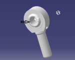
I need some help to constraint properly this spherical plain bearing to make it work. As It's obvious, I should get 3 rotational DOF for the sphere in respect of the rest of the mechanism. I've tried with the spherical joint but CATIA don't let me do the simulation because there are 3 free DOF (just what I need).

I don't know how to solve this, so if someone could help me I'll be grateful.
 

Attachments

  • CAb Rot.jpg
    CAb Rot.jpg
    29.2 KB · Views: 4
Spherical Joints do have 3 rotations (DOF), so you have to define more parts and add more joints to define 2 of those rotations.

joints.JPG
 
Thanks for the answer.

I know this point, in fact I have already added more joints. One of them is rigid so the sphere is limited to the same movements of the other part (only one rotation), but it doesn't work.
 
Can you provide a picture of your mechanism, or a little sketch of all the parts and how they are connected ?
 
In the picture you could see an U wich will be rigid joined with a cockpit (because this is for a race simulator), and in the other free part will be a linear actuator like SCN6 one.

I don't know if this could clarify the situation a bit...CR2.jpg
 
OK, there are two parts; the fixed U, and the Rod. With this mechanism, the Rod still has 3 degrees of freedom.

What does the Rod connect to? And how is that part connected back to the fixed ground? (there should be a closed loop between all the parts if you want to solve the kinematic motion.) After the rest of the parts added, add some more joints in order to reduce the DOF down to 1.
 
Last edited:
We have the U in the picture and on the other side a rod of a linear actuator. This actuator will be connected to another Spherical plain bearing (like the one on the picture) and this will be connected with the ground.

This solution is necessary because we have to let the actuator move, if we take out this the system will break.
 
Sorry, but I still don't understand the mechanism and how the parts move. Could you attach a picture of ALL the parts.

I understand and agree with the use of the actuator.
 
Last edited:
I have to guess the blue cockpit rotates about the base, which completes the mechanism loop.

Here's how I would define the kinematic joints:

(oops - my original post was incorrect, and would only work if all the Revolute axis were parallel. Below is my corrected solution, which should work all the time)

Base is the fixed part
Spherical joint between Base and Lower Actuator
Prismatic joint between Lower Actuator and Rod
CV Joint joint between Rod and Cockpit **
Revolute joint between Cockpit and Base, and Angle Driven command

** if you use a Spherical joint here, you end up with an extra rotational DOF. Using a Revolute (or U Joint) will lock up the mechanism with 0 DOF. The CV Joint will cancel out the unwanted DOF and allow the desired motion.
 
Last edited:

Articles From 3DCAD World

Sponsor

Back
Top