Continue to Site

Welcome to 3DCADForums

Join our CAD community forums where over 25,000 users interact to solve day to day problems and share ideas. We encourage you to visit, invite you to participate and look forward to your input and opinions. Acrobat 3D, AutoCAD, Catia, Inventor, IronCAD, Creo, Pro/ENGINEER, Solid Edge, SolidWorks, and others.

V5 Assembly Help

DannyB

New member
Hello

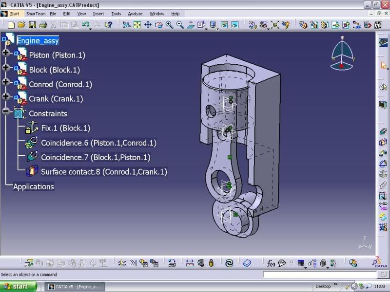
I am new to using Catia and I'm starting out by using V5 R12 and doing a tutorial of a basic piston, con rod, crank and block parts assembly.

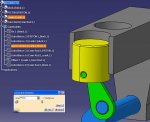
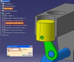
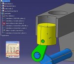
When creating the assembly and trying to move the parts I have hit a stumbling block. I can't drag or manipulate the parts (in any plane) even though they have no constraints. I can't find any setting that would prevent this.

Anyone have any tips on where I could be going wrong ?

Thanks
 
Please attach a screen shot of your assembly (including the tree) to help us understand what's going on.

R12 is a pretty old release - is this what you use at work or school?
 
Hi

This is what I'm working on. It's an old release we have on a pc at work.

CatiaScreenShot.jpg
 
post 1

OK Danny, I think I understand what you're trying to do and I have 3 options for you to animate the motion of your assembly.

1. edit the rotation constraint between the crank and block, and you can animate the assembly if you quickly increment the angle

2. use the Manipulation tool to rotate the crank by dragging it with the cursor

3. use the DMU Kinematics workbench to make this real easy

(I'll explain the first two options in a following post)

Below is a picture of my assembly that I did with R18. There might be some minor differences with your old release.

I notice your constraints are not correct; there are a couple constraints missing, and I'm not sure what the Surface Contact constraint is doing for you. Look at my assembly and try to constrain your assembly in a similar way. Make sure you add a Angle constraint between the Crank and Block - I think this is the input motion for this mechanism. (I made my Angle constraint between the vertical plane in the Crank and the vertical plane in the Block)
 

Attachments

  • kin.jpg
    kin.jpg
    112.3 KB · Views: 11
Last edited:
post 2

One way to manipulate your assembly to simulate the motion is to edit the constraint that defines the input. If you edit it quickly, you can make a simple assembly like this move pretty fast.

Assuming you have all the parts in the assembly constrained correctly.....

First, go to Tools + Options + Mechanical Design + Assembly Design and make sure the Update option is set to AUTOMATIC

Double-click on the Angle constraint that will define the input rotation of the crank. Right-click in the input box, and change the step value to 10 degrees (something not too large but not too small either)

Now click the little up triangle to step the rotation of the crank 10°. If everything is constrained correctly, all the parts should move with respect to the fixed part (the Block). Refer to the attached picture

Continue clicking the little up or down triangle to rotate the crank and drive that piston up and down.

One advantage to this method is that you can enter a precise input (like 135°) and then measure the exact location of the other components, such as the piston.

(another option will be in a following post)
 

Attachments

  • kin1.jpg
    kin1.jpg
    114.3 KB · Views: 8
Last edited:
post 3

Danny, I think this is what you were having problems with - using the Manipute tool in the Assembly Design workbench. So here's some help for you.

Again, make sure you have your assembly fully and correctly constrained. It should be similar to the picture in my previous posts.

Before we can manipulate the fully constrained assembly, we have to Deactivate the Angle constraint. If we don't do this, the mechanism will remain locked at it's current position.

Now click the Manipulate icon.

I like to use the Drag Around Any Axis option in the lower-right corner of the panel. After you click this icon, hold the cursor over the crank axis and select the line that appears. This is the line we'll be dragging (rotating) around. See my attached picture

Turn on the option With Respect To Constraints, so all the other parts move also

Now, move the cursor to some outside spot on the Crank, hold the left-mouse button down, and drag the Crank to rotate it about the line. All the other parts should move based on how they are constrained to each other.

Note: this works pretty well with a simple assembly containing simple parts like this. The more parts and more detail that you add, the slower the system will respond to this type of manipulation.
 

Attachments

  • kin2.jpg
    kin2.jpg
    118 KB · Views: 4
Last edited:
Thanks for your detailed reply. I'm not having a problem with simulating the assembly or what constarints I need (hadn't been fully defined at that point).

I'm having the problem of not being able to manipulate the parts (by moving about any axis). It just seem I can't pick and drag them any way.
 
I guess I misunderstood your use of the term "manipulate" Danny

If you just want to move parts around in your assembly, use the Compass. (This is one of the first things that are taught in an Assembly Design class)

First, make sure you're in the Assembly Design workbench. Then, drag the red dot of the compass down to the part you want to move. (the compass should turn green, and the part should highlight in the tree) Now, drag the part using the components of the compass:

a. slide the part by selecting and dragging along the U, V, or W axis, or

b. rotate the part by selecting and dragging the U, V, or W curve, or

c. drag the part by selecting and dragging the UV, VW, or UW plane

When you have the parts moved where you want them, use View + Reset Compass to put the compass back in the corner

When you Update the assembly, all the parts will move back to their constrained positions
 
Last edited:
I have figured out using the compass on the parts within the assy. I still can't seem to manipulate parts buy dragging them with the manipulate tool with repect to constraints. When selecting this function I can't seem to pick the axis or part to drag it.

I am trying to self-tech myself using an old tutorial borrowed from a colleage. This tutorial doesn't explain the compass function ! I can only assume it was to supplement a design class.

Thanks for the help
 
Did your screen every grey out?

Sometimes accidently you can switch off the compass and the movement function if it greys out.

What you need to do is drag your compass back to the original place it starts off in.

Then double click the compass or the 3axis arrows at the bottom right hand corner or the top right hand corner of your screen.

Then you should be able to drag and drop the compass back on the parts to move them around for approximates.

But make sure you do put constraints between your surfaces in order for you to Simulate properly and for more accurate positioning.

Also another thing, I am hoping your not expecting to have a fully moveable model but just using the compass. Catia doesn't work like this you must utilize your simulation tools.

Hope it helps.
 
I have the same problem. If I click the "manipulate" icon nothing happens (normally the small window with the move/rotate options should appear). Also it seems the manipulation box isn't working in the assembly design, it simply doesn't appear. But the box is there and works when I am in "product structure" mode.

To make it clear I just want to move an object on the screen, so i can e.g. select a surface for constraints aso. I don't want to animate anything (and I think it's the same with Danny).
 

Articles From 3DCAD World

Sponsor

Back
Top