Continue to Site

Welcome to 3DCADForums

Join our CAD community forums where over 25,000 users interact to solve day to day problems and share ideas. We encourage you to visit, invite you to participate and look forward to your input and opinions. Acrobat 3D, AutoCAD, Catia, Inventor, IronCAD, Creo, Pro/ENGINEER, Solid Edge, SolidWorks, and others.

Wireframe Challenge!!

Wallybanger

New member
So here's the scoop. This is a lot like the roll cage topic but I didn't want to hijack. I'm planing to build an airplane but before I start construction, I want to model the thing. I had already started a model (actually invested a lot of time in it) but I was getting errors that were really starting to piss me off. So i rethought how I was going to go about modeling it.

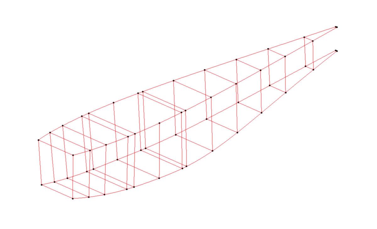
I've started by making a Wire frame of all the cross members in the fuselage:

wireframe.jpg


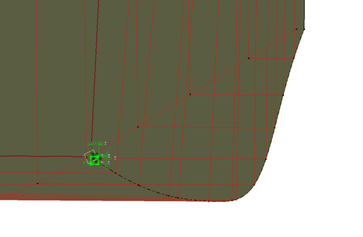
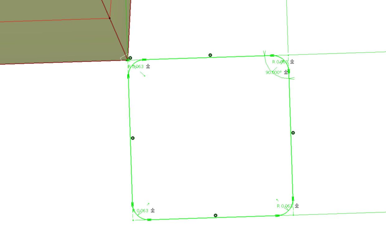
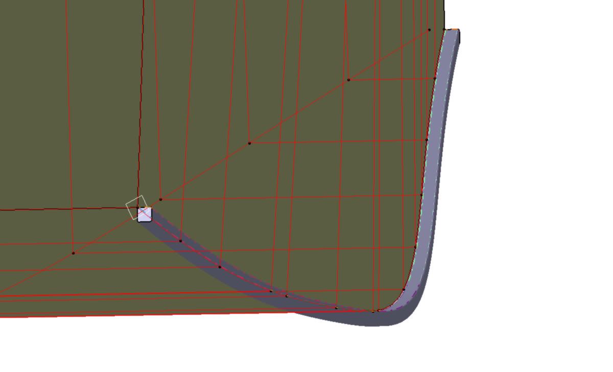
Basically, all of those lines need to become 5/8" cross members and I REALLY don't want to individually model them all again. I know I can use the Rib feature to create what I want:

x-member1.jpg


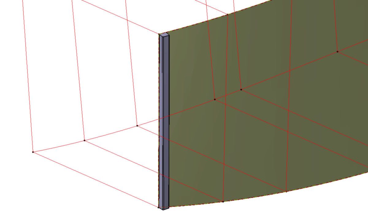
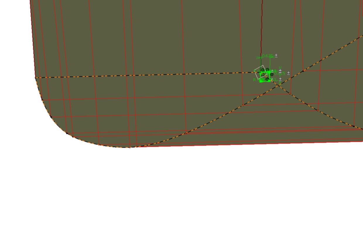
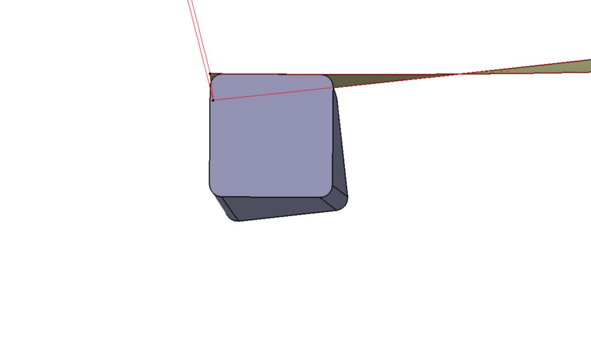
Notice how the x-member twists as it goes between the curves of the top and bottom of the fuselage:

x-member2.jpg


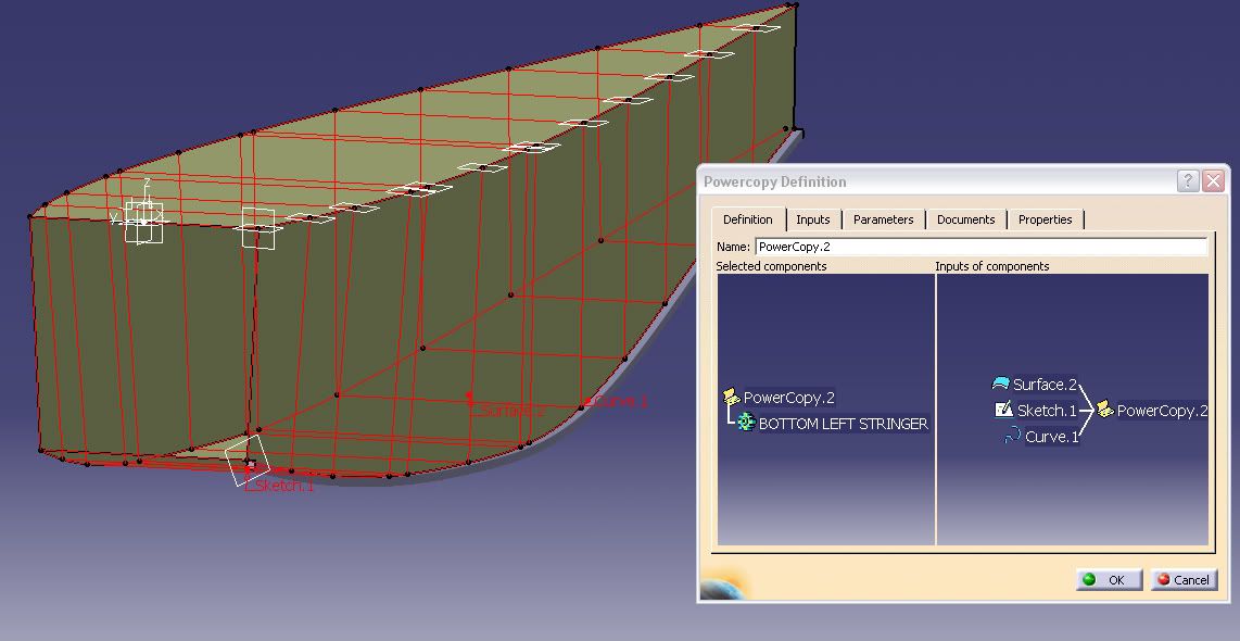
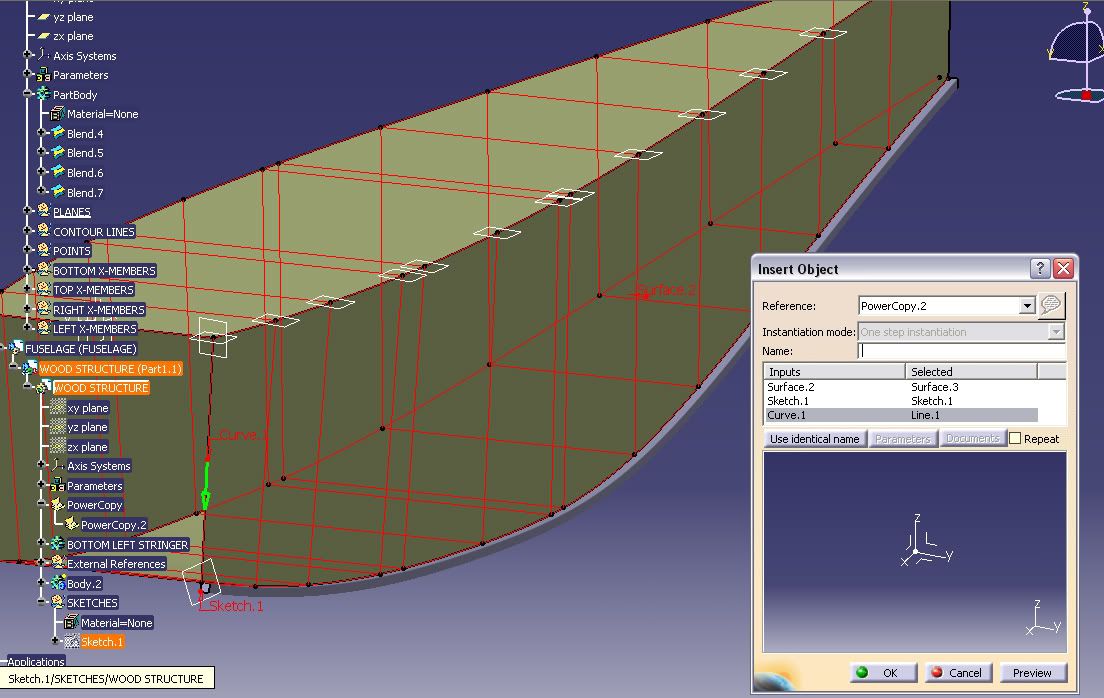
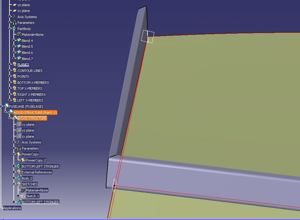
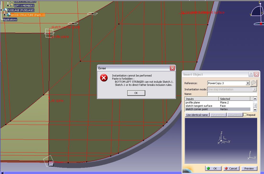
So is there any method i can use to speed up the creation of these ribs? I don't want to have to sketch the contour of the rib every single time... is there any way to repeat the rib by only selecting the line and the surface that it follows?

I was modeling each rib as an individual part but I'm starting to think that this'll be way too labour intensive! As long as each member can be individually measured for fitting I will be happy.

Any idea's would be greatly appreciated

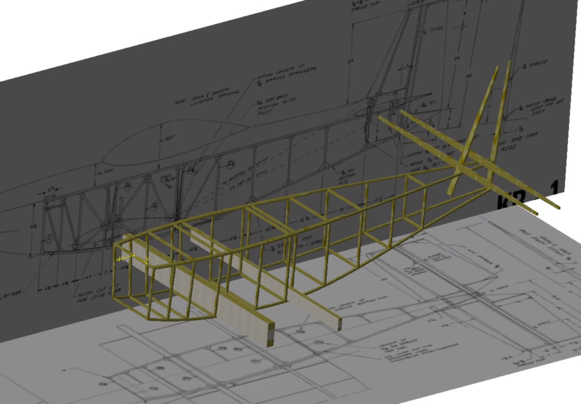
Oh, and here's what I have for the other model. I'm going to salvage what I can and 86 the rest:

PROGRESS002.jpg
 
here's any easy way to do it

I would use a PowerCopy to duplicate the twisted Rib and it's parent Sketch. This should simplify the task, by only requiring that you select the cross member as input for each Rib.

To save time, I would also mirror the left side members to the right side.

Since this is just to prove out the design, I'd probably model everything in a single CATPart file.

I'm curious how you attach all the cross members together? Do you have to cut them back to fit inside the stringers?

Any other suggestions?

Mike: how did you do it?
 
Hey MrCATIA, thanks for the reply, I will have to look into the "power copy" and see what I can dig up.

So if I were to power copy each rib into it's own partbody, could I then convert them into individual CATParts later if I so desired... or would I run into errors and problems? how much work would it be?

I'm curious how you attach all the cross members together?
You mean physically, when i actually build it? I believe I'm supposed to build the right and left sides individually... lay the materials flat on a table, cut everything to length and then glue all the wood together with epoxy. Everything then gets gusseted. then crossmembers are cut to length and glued between the left and right sides

Any other suggestions?

Mike: how did you do it?
Hunh? Don't really understand what that means....
 
Another suggestion: include the cutbacks into the PowerCopy

Hunh? Don't really understand what that means....

Maybe another member can offer other methods to this challenge?

Looking at the last picture you attached, I'm curious how you got this far. It looks pretty good to me!


So if I were to power copy each rib into it's own partbody, could I then convert them into individual CATParts later if I so desired... or would I run into errors and problems? how much work would it be?

You'd have to copy and paste each PartBody into a new CATPart file - a lot of work for all the members you have there. If you know for sure that's what you want, I'd do that up front:
  1. make a new part
  2. copy and paste with link the wireframe member and tangent surface
  3. Instantiate the PowerCopy from the wireframe document
  4. repeat for each member
  5. assemble all members into a Product
  6. add the gussets (hopefully you can use the same one multiple times)

This is an awfully big airplane to glue together - is this an RC project?
 
in response to separating this out after you are done.

i have had to do this a few times and the method i find easiest is to start buy putting the geometric set under the part then build one, then you copy and paste the whole part and modify it making sure not to grap the previous parts. after you build the model in this fasion so that each part is self contained in a single cat part file is is easy to copy each part out in to a new file.

if this is too much work then you can always just save the model 108 times for each member, remove all but what you want and use the "delete Useless elements" comand under the part design work bench

iether way is long and painfull.

but if you don't need history then i might suggest righting out a step file and set you prefferances to read it in as an assembly. this will give you all the parts but they will all be dumb solids with no value.

i hope this helps a little and sorry it is so long winded :rolleyes:

GOOD LUCK
 
progress

OK, I've been playing with this a bit and I think I need some help with power copy.

I want my first rib to run down this curve:
001.jpg


I made a plane normal to that curve on the end point of the line.
I then made this sketch for my profile.
002.jpg

I used construction lines for the .625" square with a 90Deg ang constraint. I eliminated all of the V&H constraints. I then sketched coincidental lines and put the fillets in the corners. I could then drag my constrained profile where ever I wanted. i decided to constrain the top line of the profile to the bottom surface of the fuselage
003.jpg

and made the corner of the square coincident with the end point of the "center curve" line.

then I created my rib

004.jpg


I then went to make my power copy and chose the Body that had the rib in it
005.jpg

I didn't know what to choose here to add to the selected components thing, so I chose nothing. (later I chose the sketch of the profile, you'll see why, but when I hit ok on the power copy it gave me a bunch of errors).

so insert>instantiate from document picked my wood structure.CATpart

006.jpg


I selected the plane, sketch and "curve"
007.jpg

It worked, sorta, but even that was mostly luck.

It didn't move the sketch, which is what I think I need it to do so I went back to create the power copy and this time selected the sketch for the "components to include". The next time I tried to instantiate it asked me for a few more things... I figured it wanted those sketch constraints.... sketch plane, tangent surface and corner point. that's when I got the error.

008.jpg


Any input would be greatly appreciated!

thanks
Mike
 
You're doing pretty good, Mike. I just have a few suggestions to help you.

(I think you can do this by using the same sketch profile for all the ribs. But let's save that for the next airplane you model. For this design, let's make a new sketch for each structure.

I want to include the cutbacks in the ribs, but that's you're option. If you don't want them then ignore my cutback steps below.)

Going through the steps in your last post:

Normal Plane - good!

Profile Sketch - okay, but I have a couple suggestions

1. make the sketch a Positioned Sketch, instead of the Sliding sketch.

2. for sketch origin, use Curve Intersection option and pick the Rib curve for the reference

3. for sketch orientation, use Normal to Surface option and pick the tangent surface.

(steps 2 & 3 will put the H & V axis in the right place, so you can use them)

4. draw the sketch like you did, but now you can use the sketch axis to make it a little easier.

Rib - good!

1. If you want to add cutbacks, you could add offset planes at each end, and use SPLIT to trim them back. Or a better way (I think) is to use THICKNESS to trim the rib ends (select both end faces of rib, and key-in negative 5/8")

2. this is the point where you would follow Jagodragon's suggestion about Geometric Sets

PowerCopy definition - you're on the right track - a couple suggestions:

1. select the PartBody to copy (I didn't think of this, but this is a good idea!)

2. A good strategy is to minimize the number of inputs. So, in the Input side of the Definition panel, select the features you want to copy (so they jump to the Selected side):
- the profile sketch
- the normal plane used for the sketch background

3. the inputs you want to use should be:
- the curve to drive the Rib
- the surface to define the Rib tangency
- the point to define the normal plane

4. (optional) use the Inputs tab to rename (publish) the Inputs, with better, descriptive names

Instantiate the Power Copy - you're doing it right!

But now you should only have 3 inputs (3 things to select each time you PowerCopy a new rib:
- the rib curve
- the tangent surface
- the end point of the curve
 
Last edited:
It didn't seem to work. I followed your instructions but it wouldn't let me use lines, points, planes ext because apparently they were 'external references'. It will severely piss me off if I have to remodel everything again because catia won't let me use my skeleton to replicate these ribs. I even tried just power copying the sketch (because resketching that rib profile 40 times will be a HUGE PITA!).

there are a lot of things like this that make me think Catia is a huge turd. In Proe you can just 'repeat' stuff. I'm almost thinking I should just do this project in ProE to save myself a huge hassle.
 
Skeleton? External References? This is the first time you mentioned these! I thought you said you were doing everything in one big file.

Without the exact error message, it's difficult to help you. Try this: go to Tools + Options + Infrastructure + Part Infrastructure and turn off the option to Only Use Published Elements... (I'm guessing you're not using Publications)

How much CATIA training have you had, Mike?
Yeah, I knew about publications but I didn't publish anything. Didn't know you you could turn off "Only Use Published Elements", that's pretty cool.

Formal Catia training? Not much. I did a 1-1/2 week training course when the company first switched over to catia and I usually figure everything else out by myself. The problem is that I like to learn outside the scope of the required usage. My boss and co-workers don't even know how to do this stuff. Hope I'm not wearing you down :)

Yeah, I was going to have the wood structure in 1 product but I need the skeleton available for the rest of the plane. I'll put the model on my FTP if you want to have a look at it. PM inbound ;)
 
Without the exact error message, it's difficult to help you. Try this: go to Tools + Options + Infrastructure + Part Infrastructure and turn off the option to Only Use Published Elements... (I'm guessing you're not using Publications)
OK, I tried Tools>options>infrastructure>part infrastructure but there was no "Only Use Published Elements" option.

I tried copying all of the stuff I was using in my skeleton into the Part Body so that I could publish it. When I tried to use the power copy I got the same error

Error in Definition:
-An element with a link to an component external to the power copy has been included
Remove or isolate this element to avoid this problem.
(plane.2) in an external reference
(Curve.2) is an external reference
(Surface.3) is an external reference
 
convert PartBodies into CATParts

I've been a little busy at my paying job, but I haven't forgotten you. I need to download your files and get good instructions that work for you, but it will take a little time.

Earlier you asked about converting a single CATPart file by making each PartBody a separate CATPart file:
So if I were to power copy each rib into it's own partbody, could I then convert them into individual CATParts later if I so desired... or would I run into errors and problems? how much work would it be?

Here's a link to the German CATIAV5 Forum where someone asks the same question. About half way down is a macro you can download, and near the bottom are instructions on how to run the macro.

General: Transform multibody-part in a product.. - CATIA Assembly Design - CATIAV5 Forum
 
Last edited:
I've been a little busy at my paying job, but I haven't forgotten you. I need to download your files and get good instructions that work for you, but it will take a little time.

Earlier you asked about converting a single CATPart file by making each PartBody a separate CATPart file:


Here's a link to the German CATIAV5 Forum where someone asks the same question. About half way down is a macro you can download, and near the bottom are instructions on how to run the macro.

General: Transform multibody-part in a product.. - CATIA Assembly Design - CATIAV5 Forum
Paying job? PAYING JOB? As if I take second priority to a "paying job", unbelievable! :D in all seriousness, I really appreciate the help... time isn't an issue, this is a hobby model. I'm happy there are people like you willing to dedicate their time to noobs like me :p

Let me know if you have any problems getting those files off the FTP.

I'll have a look at that Macro. Sounds like an awesome idea! I need to upgrade my computer hax0r skills so I can write scripts, macros and monkey with Catia!

Thanks again! :)
 

Articles From 3DCAD World

Sponsor

Back
Top