Continue to Site

Welcome to 3DCADForums

Join our CAD community forums where over 25,000 users interact to solve day to day problems and share ideas. We encourage you to visit, invite you to participate and look forward to your input and opinions. Acrobat 3D, AutoCAD, Catia, Inventor, IronCAD, Creo, Pro/ENGINEER, Solid Edge, SolidWorks, and others.

Drafting of groove

nadim6

Newbie
Hello everyone!

I'm a beginner and need some help for drafting on Catia.
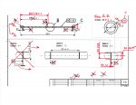
I don't really know if what I did is right with the snap ring groove.

I put the 1.1 (x4) and 14.3 (x4). Also, I had some difficulties with the scales, so I had to put these A*, B* and C* to make it clear. Should I change this ?

Is that correct or should I draft it 4 times for each groove ?
Also, if you may see any other mistake, don't hesitate :)

Thanks a lot for anyone's help!

(P.S. My Catia workspace is in French)

Capture d’écran 2020-06-01 à 16.48.27.png
 
Last edited:
Not too bad for a beginner. Here's some corrections to make:

1. delete the A B C boxes (they indicate datums, which is not what you are trying to represent)

2. using 4X for the groove width and diameter is good, since they are all the same size. Detailing each groove individually is not good.

3. the view is the upper-right corner is the end view (I think). Since it's a different scale than the front view, label the view as view A-A and add the view labels on the left.

4. delete Detail A, and re-dimension the groove in Detail C

5. make Detail C a little bigger to show the end of the shaft. I think both ends are chamfered, so add the chamfer dimension (2X)

8. change the 305,9 dimension to go to the same face as the 65 dimension

9. I don't know what a js6 tolerance is on the 15 diameter dimension. (maybe just j6 ?)

10. delete those extra symbols on the bottomimg001 (2).jpg
 
Not too bad for a beginner. Here's some corrections to make:

1. delete the A B C boxes (they indicate datums, which is not what you are trying to represent)

2. using 4X for the groove width and diameter is good, since they are all the same size. Detailing each groove individually is not good.

3. the view is the upper-right corner is the end view (I think). Since it's a different scale than the front view, label the view as view A-A and add the view labels on the left.

4. delete Detail A, and re-dimension the groove in Detail C

5. make Detail C a little bigger to show the end of the shaft. I think both ends are chamfered, so add the chamfer dimension (2X)

8. change the 305,9 dimension to go to the same face as the 65 dimension

9. I don't know what a js6 tolerance is on the 15 diameter dimension. (maybe just j6 ?)

10. delete those extra symbols on the bottomView attachment 2508
Thanks so much for your answer. It's much better now ! But I still have a little question about the A*, B* and C* I used. Can you give me an exemple of when to use these ?
Related to this, I don't understand how one knows if the 307 dimensions you put refers to the left or right side of the groove. The front view is very small, and it's almost impossible to see this, so that's why I made these A* B* and C* to show on the detailed views to what they refer..

For the rest, it seems clear! Thanks a lot once again :)
 
But I still have a little question about the A*, B* and C* I used. Can you give me an exemple of when to use these ?

The square symbol with arrow identifies datums (fixed references) that are used with GD&T tolerances. Using that symbol for any other purpose is very confusing. Instead, you could use a different shape (hexagon?), or spell out "SURFACE A" and "SURFACE B". But the proper drafting method to show small features, is to add detail views at larger scales (exactly like you did for Detail B and Detail C)

I don't understand how one knows if the 307 dimensions you put refers to the left or right side of the groove.

Standard dimensioning practice is to dimension from the same surface, so the 307 dimension should be to the same side as the 65 dimension. Plus it is more likely that dimension values are nice, round numbers - so I made an educated guess that 307 was the intended value instead of 305.9. You could add a half dimension as a reference to add the 307 dimension in Detail B, which will clearly show both the 307 dimension and 65 dimension both referencing the right side of the groove.
 
Last edited:

Articles From 3DCAD World

Sponsor

Back
Top