Continue to Site
Follow along with the video below to see how to install our site as a web app on your home screen.

Note: this_feature_currently_requires_accessing_site_using_safari
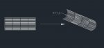
The easiest way for a simple part like this is to use the Sheetmetal workbench.