Continue to Site

Welcome to 3DCADForums

Join our CAD community forums where over 25,000 users interact to solve day to day problems and share ideas. We encourage you to visit, invite you to participate and look forward to your input and opinions. Acrobat 3D, AutoCAD, Catia, Inventor, IronCAD, Creo, Pro/ENGINEER, Solid Edge, SolidWorks, and others.

Catia PITA

Wallybanger

New member
Hey Folks, First post here but I'm sure I'll be spending alot of time here, this is a neat site.

So the company I work for just switched to Catia V5 from ProE2001 and I'm not overly excited about the whole thing. It seems like stuff that was EASY to do in ProE has become a major PITA.

Some of the things that are really bothering are in drawing mode... When I try dimensioning stuff in a drawing there doesn't seem to be a "Midpoint" option. Anyone know how to dim to the midpoint of a line? Also, for dimension text, is there a way to have stuff jump to a new line as opposed to just one giant line for vertical dims? Also, is there a way to have sketches (Non physical geometry) appear in a sketch with a solid model?

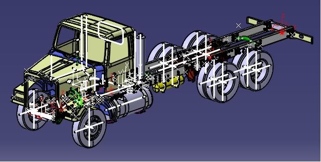
I'm also dealing with models in assembly mode and I can't find an easy way to turn on/off Datums, points, axis etc. Any pointers you guys could offer would be a HUGE help! A really busy model and be incredibly distracting.....

This is what I have to contend with
truckcat.jpg


One last question... Is there a transferable Catia Config file? There was a proe2001.ini file that could be moved from one computer to another to set up user interfaces, graphics options and stuff like that.

Thanks
Mike
 
Welcome to the world of CATIA, Mike.

I know what you mean about learning something new. I took a ProE class a couple years ago and I thought ProE was a PITA. I had the same opinion when I switched from WordPerfect to Word, and when they took away my drawing board and replaced it with my first CAD system.

I'm sure that with some good training and practice, you'll learn that CATIA isn't all that bad and you might find something that CATIA does better than ProE.

I'll try to help with some of your questions:

Mid point of a line

CATIA has 'SmartPicks" and I think there is a midpoint option at least with Sketches. (I'm not sure about drawings.) You could also make a 3D points as a "middle point" and then project the 3D point into the drawing.

Multiple lines of text

This depends on how you do it. If you add the text as a Dimension property, I think it is limited to a single line. If you add an individual Text note, you can make it as many lines as you wish, and then add a Positional Link to anchor it to the dimension.

Sketches appearing with Solids

By default, CATIA hides a sketch when it is used to make a solid feature. But you can always Hide/Show to make the sketch appear again. You can also use Tools + Show to display all sketches.

If the sketch is part of a Geometric Set, make sure the Geometric Set is not hidden.

Datum geometry in large assemblies

I've been told that ProE has a feature called "skeleton" ? Many CATIA users have a similar method; make a single CATPart that contains the Datum points, axis, centerlines, etc. Add this to your assembly. You can also make links (external references) to this "skeleton" file, so everyone can use it to drive their part designs and all the parts can be easily manipulated by simple changes to the "skeleton."

hope this helps!
 
Last edited:
MrCATIA, Thank You!
Those are some really helpful points there... some of which have lead me to more questions ;)

When you refer to SmartPicks do you mean when you use the arrow keys in a way that replicates "Query Select" in proE (ie. the list of selectable stuff that pops up)? Yeah, What I've been doing is creating 3D points but that can get time consuming.

I discovered the individual text notes and it again came down to time consumption. Didn't know about the positional links though.

OK, That Tools>show/hide was a function i had forgot about! It will show ALL of the sketches though, right? There's no way to display individual sketches? The reason I need this is because I have 3D points driving the line AND because I need to to appear BEHIND other parts that pass in front of the line. So far I have been creating .001" shafts to portray the line.

OK, The Skeleton idea is interesting..... The only problem is that we use another program to automatically generate the large assemblies that I have to modify. I'm not actually manually creating all of the crud that I want to hide. Is there a way to Transfer or copy the stuff to the Skeleton? I haven't tried it yet but I'm hoping that the tools>Hide/show will sort me out.

OK, you've definitely given me some food for though. The only other thing that I ran into today (and I'm thinking about starting a new thread on the subject) is I'm wondering if you can use an XML or similar spreadsheet to drive a model? I made something today that resembles your 'Skeleton' idea and I would like to be able to drive points with a spreadsheet. Can you do it? Is it reasonably easy?

Cheers,
Mike
 
The Complications Never end! I'm having great difficulties getting models modified on V5R18 to open with V5R16.... Stupid Dassault and their lack of foresight ;):D

I've managed to blunder through some step conversion that have actually worked suprisingly well (Actually functioning in a manner I've never seen step files operate) but I now have one assemblie/part that I can not get R16 to open. I REALLY wish the documentation was better. Am I going to have to get 3rd party converter? I can understand R16 not opening R18 files but I Can't understand R18 not being able to save in an Rx compatable format....

Sorry for all the questions but I really do appreciate the help.
 
When you refer to SmartPicks do you mean when you use the arrow keys in a way that replicates "Query Select" in proE (ie. the list of selectable stuff that pops up)?

SmartPicks are the little blue symbols that appear in Sketcher and Drafting. They let you know when on a point, or tangent, or horizontal or coincident, etc.

The arrow key feature is called the Pre-Selection Navigator, which lets you cycle through everything that is displayed in front of each other and select something that is behind other things.
 
OK, That Tools>show/hide was a function i had forgot about! It will show ALL of the sketches though, right? There's no way to display individual sketches? The reason I need this is because I have 3D points driving the line AND because I need to to appear BEHIND other parts that pass in front of the line. So far I have been creating .001" shafts to portray the line.

You have lots of options for hiding/showing things in CATIA. TOOLS + HIDE (and TOOLS + SHOW) will hide/show all SKETCHES (or whatever you pick). Once all the sketches are hidden, you can always select one sketch and show just it.

You can also group Sketches into one or more Geometric Sets, and hide/show them them that way.

Or, you could use Layers and Visualization Filters to display certain things.

Lots of flexibility.
 
I have 3D points driving the line AND because I need to to appear BEHIND other parts that pass in front of the line. So far I have been creating .001" shafts to portray the line.

Mike, I don't understand why you're making small shafts to represent a lines :confused:

You can change the graphic properties of lines and points and any graphic feature to make them standout. Change the color, thickness or style of lines.

Once you become more familiar with Part Design, I'm sure you'll find that Points and Lines are not as necesary are you think (unless you do alot of GSD surface modeling)
 
OK, The Skeleton idea is interesting..... Is there a way to Transfer or copy the stuff to the Skeleton?

You can copy stuff from your part to the Skeleton with Copy & Paste Special, As Specified.

Once it's in the Skeleton, Publish it. Then copy it back to your part with Copy & Paste Special, As Result With Link. This will put it in the External Reference branch of the tree, indicating that it's linked geometry. Once you start using the linked geometry (the "Skeleton method"), a new tool for you is EDIT + LINKS.
 
MrCATIA, thanks again for all the help.... but I'm getting frustrated and overloaded. I still can't get over how much the documentation sucks. I think part of the problem I'm having is that these ridiculous companies I work for like to "Customize" the interface of the software and all that does is confuse people.

With the Tools> Show/hide, the only time I can see it/use it is when I have a PART selected.... it will only work for parts. I want it to work for the whole damn assembly but it won't.

As I type this I'm fighting with a drawing... trying to get the crazy thing to display planes so I can dimension to them because a circle, displayed from above (So a line) is throwing these damn dimension end points all over the place. I really don't know what these people were thinking when they designed this software.

Erg, I don't know how to group stuff and I can't figure out how to use Layers. ProE was SOO much easier for stuff like that. Make a layer, add crap to it, select what you want to add...

Yeah, I don't see any smart pics.

OK, Tools>Utility has the downward compatibility thing. Thanks, I'll give it a try!

I'm making shafts to represent lines because I have no idea how the visibility junk works in drawing mode. the only stuff I can get to show up is solid geometry... yeah, frustrating!

Apparently I still Have a lot to learn and it's a slow arduous process. The fact that I'm posting on a Catia message board instead of dealing with the companies I work for says a lot on it's own. Sorry for the Rant but I needed to get it out of the system.

One of the only things that actually seems good is that Design Chart thing. I was playing with it and I think I can make it do what I want... thanks!

It would be nice if there were good menus and I were able to browse, play with stuff and learn that way but unfortunately Catia's unnecessary complication makes that an Impossibility. Erg, Again, sorry for the rant.
 
As I type this I'm fighting with a drawing... trying to get the crazy thing to display planes so I can dimension to them because a circle, displayed from above (So a line) is throwing these damn dimension end points all over the place. I really don't know what these people were thinking when they designed this software.

I'm making shafts to represent lines because I have no idea how the visibility junk works in drawing mode. the only stuff I can get to show up is solid geometry... yeah, frustrating!

Try this when working with drawings, so you won't have to make .001 shafts:

1. For new drawings, go to TOOLS + OPTIONS + MECHANICAL DESIGN + DRAFTING and click on the VIEW tab at the top. In the VIEW tab; turn on the option PROJECT 3D WIREFRAME. GENERATE AXIS and GENERATE CENTERLINES are also helpful.

2. For existing drawings, right-click on a view and choose PROPERTIES. Click on the VIEW tab. In the middle of the panel is the option for 3D WIREFRAME - turn this on. Click OK and UPDATE the drawing. Repeat this for every view on the drawing.

With the Wireframe option turned on, you should now get points, lines, circles, etc projected onto your drawings. But you won't get Planes in drafting.
 
Last edited:

Articles From 3DCAD World

Sponsor

Back
Top