Continue to Site

Welcome to 3DCADForums

Join our CAD community forums where over 25,000 users interact to solve day to day problems and share ideas. We encourage you to visit, invite you to participate and look forward to your input and opinions. Acrobat 3D, AutoCAD, Catia, Inventor, IronCAD, Creo, Pro/ENGINEER, Solid Edge, SolidWorks, and others.

Complex loft with curved terminus

Cad2homebuild

New member
Hello.
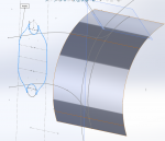
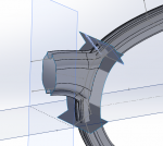
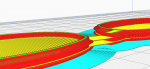
I hope that a highly skilled designer here can advise me on a method for creating a loft that terminates at a curve. I'm creating eyeglass frames and the bridge needs to merge with the eyeglass surround. I can't extend past and cut the overflow because the loop has a complicated profile. I thought about one method of creating four surrounding sketches, but don't have enough experience with that. I intend to 3D print this and run steel wire where the circles are as a reinforcing element.
If you can name a technique to solve this, then I'm happy to research it, I just don't know what feature to use.
Thank you very much in advance for the help.
 

Attachments

  • Screenshot_bridge-curve2surface.png
    Screenshot_bridge-curve2surface.png
    180.8 KB · Views: 2
I managed to enclose it with bounding surfaces. However it wont mirror which likely means that it isn't a solid. Neither knitting surfaces nor bounding will work for this
 

Attachments

  • BridgeCompleteSurface.png
    BridgeCompleteSurface.png
    107.2 KB · Views: 1
One can tell its not solid as you have open edges (the blue edges). However, just for clarification, you are able to mirror surfaces in SolidWorks.

My initial thoughts wouldn't have been to use a boundary surface, though It's very hard to tell what you have done/want to achieve from just the pictures,

You have the profile at one end, I would look at creating the profile at the other end, probably by trimming that curved surface in your inital picture

1590954489120.png

that way you can loft between the two profiles and use your side curves as guide curves

Also I would really recommend adding realtions and dimensions to your sketches to fully define them where possible. This is just good common proactice for normal sketches, but very useful in f lofts and sweeps to avoid any twisting.

Attach your part and I would be happy to take a look if i get chance, that way i could give you better advice
 
Thank you Cadasio for your reply. Somehow I was able to build a solid with boundary surfaces. It does show up as a solid. I mirrored both the glass border and the half-bridge. Then I used combine to unify it into one element. However after exporting to .stl and opening in Cura, there is a message stating that the part is non-manifold. When I do a construction preview it shows the 1st half of the bridge missing (see picture).
It hasn't been possible to attach the file here, so I have it on a server which you can access via this link.
I thank you for your thoughts or advice.
 

Attachments

  • glasses-print_NonManifold.png
    glasses-print_NonManifold.png
    299 KB · Views: 2
I've had a quick look, and since it's a solid in SolidWorks, then that would suggest its OK as far as geometry goes - though you may want to look at some of the small edges created.

1592149911560.png

the stl is also fine as I viewed it on https://www.viewstl.com/ and it looked the same.

I have no experience with Cura, but looks like the problem is with that so i would contact them / their forum
 
Thank you everyone.
I figured out a solution. I rebuilt the bridge as a solid and roughly cut out the lens curve. Then I saved each lens curve as a right & left file. I put all three files into an assembly file with constraints and saved that as a part file. Then I used combine to merge the three solids together.
A very roundabout process, but it works.
 
I have a new question to ask regarding this subject. Because the 1st & 2nd builds were not perfect, I would really like to find a solution that doesn't involve the process above. I briefly had found a fix, but that file was lost.
I have a list of several files here which should have all of the information - http://towardzeroimpact.net/SolidworksQuestion/
The file '0620c' is the one which was combined from three part files but does not allow me to go back and adjust the sketches. The file '0620e' has all of the sketches and changes, but I cannot get thicken to create a solid from the four bounding surfaces in order to make the eyeglasses bridge. If someone here can tell me what I can do to make the surfaces function better I would deeply appreciate it.
thank you in advance
 

Articles From 3DCAD World

Sponsor

Back
Top