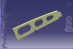
There doesn't seem to be a lot on this topic. I'm hoping I can find some help here.
I'm creating a sheet metal flat pattern from a solid in V18. To do this, I extract a surface from the solid, (from the underside of the 3D sheet metal solid) offset it half the thickness of the part to get a "neutral" plane and then run the unfold function on that. Here's where the problem arises. To keep it simple, picture a 4" X 4" X .09 piece of sheetmetal with a 90 degree bend 1" from the end with a 10 degree bias. The area that will be unbent (top surface) will have a 1" radius cut into one side with two 1/2" tabs on each side of the radius that have a 3/16" dia. hole in them. These tabs/holes are used to locate the flat pattern to the tooling.
When I invoke the unfold function, the origin and direction are automatically selected. I don't understand how and would like an explanation on this too. You can select other surfaces and edges to change these valuse but, also, don't really know what to select. The problem arises when I select OK to unfold the surface, the radius and tabs are "streched". In the real world bending operation, these features would remain stationary. What now happens is that the flat pattern will not fit the bending tooling due to this stretching. Does anyone know what I need to do to keep these features fixed and only create a flat pattern of the bend on the front with the tabs and radius staying in place?
Thanks in advance.


