Continue to Site

Welcome to 3DCADForums

Join our CAD community forums where over 25,000 users interact to solve day to day problems and share ideas. We encourage you to visit, invite you to participate and look forward to your input and opinions. Acrobat 3D, AutoCAD, Catia, Inventor, IronCAD, Creo, Pro/ENGINEER, Solid Edge, SolidWorks, and others.

Creating a flat pattern in V18

zumkatze

New member
There doesn't seem to be a lot on this topic. I'm hoping I can find some help here.

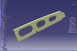
I'm creating a sheet metal flat pattern from a solid in V18. To do this, I extract a surface from the solid, (from the underside of the 3D sheet metal solid) offset it half the thickness of the part to get a "neutral" plane and then run the unfold function on that. Here's where the problem arises. To keep it simple, picture a 4" X 4" X .09 piece of sheetmetal with a 90 degree bend 1" from the end with a 10 degree bias. The area that will be unbent (top surface) will have a 1" radius cut into one side with two 1/2" tabs on each side of the radius that have a 3/16" dia. hole in them. These tabs/holes are used to locate the flat pattern to the tooling.

When I invoke the unfold function, the origin and direction are automatically selected. I don't understand how and would like an explanation on this too. You can select other surfaces and edges to change these valuse but, also, don't really know what to select. The problem arises when I select OK to unfold the surface, the radius and tabs are "streched". In the real world bending operation, these features would remain stationary. What now happens is that the flat pattern will not fit the bending tooling due to this stretching. Does anyone know what I need to do to keep these features fixed and only create a flat pattern of the bend on the front with the tabs and radius staying in place?

Thanks in advance.
 
Hi there

It sounds like you are using the unfold command from the surface design workbench which does not allow for material stretch and only unfolds surfaces. Yu need to use the Sheet Metal Design workbench which does have a method of converting a part design(Pad) into a sheetmetal solid which can then be folded and unfolded. I will also allow the creation of a flat pattern view on your drawing sheet. Wen you activate the Sheet Metal workbench there is a command called Reconize that you use to convert from part design to a sheetmetal design.
 
Depending on which licenses you have, you should be able to develope the flat pattern several different ways.

As Colin suggested, the Generative SheetMetal workbench is one method. As Colin said, this method offers many automatic sheetmetal capabilities.

Or as you described, the Develop toolbar in the Generative Shape Design workbench (with the Develop license) should work as well, but more in a manual mode.

Here's what the Help documentation says about the origin and direction:

Information on the surface to unfold is displayed in the dialog box:

Origin: point on the surface to unfold. If no specific origin is selected, it is set to Default. By default, when possible, a corner of the surface to unfold is selected.

If a target plane is defined and a projection is possible, the origin is defined as the projection of the point, selected as the origin on the surface to unfold, onto the target plane. If not, the origin of the axis system of the target plane is selected as the default origin.

Direction: edge of the surface whose extremity is the point. If no specific direction is selected, it is set to Default. By default, when possible, an edge of the surface to unfold is selected.

If a target plane is defined and a projection is possible, the direction is defined as the projection of the tangent to the selected edge onto the target plane. If not, the direction of the target plane is selected as the first direction of the axis system of the target plane.

By default an origin and a direction are selected, and the result is positioned such as this origin and its image as well as the tangent to this direction and its image are coincident.​

I like your method, but I would suggest a different approach. First, simplify the "bent" surface by ignoring the holes and tabs, and extent the surface beyond where the tabs are (sort of like a rough stock piece). UNFOLD this extended surface, to create the flat surface. Then project (UNFOLD) the edges of the part, including the tabs and holes onto the flat surface to get the flat pattern.
 
Last edited:
Thanks to you that replied with your suggestions. I started experimenting with Colin's tip on using Recognize. Unfortunately, I didn't get too far with it. When I selected the part to "recognize", it only got some of the features and left the others alone. When I unfolded the few that were selected, it unfolded perfectly which told me this is something I need to investigate further because it seems to work. So, with that, are there any tips/tricks in using the recognize function I need to know in order to get the entire solid to be recognized? For instance, what would be considered a reference face? Do I want to remove a face or keep a face (or both)? Should I extrude the part before working with it? As a little more info on the part, it is a thick surface that was generated from various sweeps, joins and splits. I added a screenshot of what I'm working with.

Again, thanks for your assistance.
 

Attachments

  • recognize.jpg
    recognize.jpg
    154.7 KB · Views: 12
Mr. Catia,

This sounds EXACTLY (ALS) what I need! Thanks! I have the purchasing guy on the phone with Incat as I type to get a license. I'll keep you posted as to how it works out. Again, thanks!
 
I do not know what you have said.It would be better if there are some pictures
This is a very old thread... I'm surprised there is still a little bit of interest.

An update to the original problem. I scrapped trying to use the unflod/recognize, etc functions in Catia V5. I went with a 3rd party solution that integrates with Catia. It utilizes the Analysis license and computes the flat pattern result utilizing a FEM with various inputs of the material you are bending and other real-life conditions. I have done HUNDREDS of flat patterns with this solution with excellent results!

The Catia unfold function, IMO, is useless for this task. My predecessor in my job relied upon the unfold function. I've spent countless hours fixing all the mistakes he created over the years with my new program. Needless to say, our product quality has immensely improved.
 

Articles From 3DCAD World

Sponsor

Back
Top