Continue to Site

Welcome to 3DCADForums

Join our CAD community forums where over 25,000 users interact to solve day to day problems and share ideas. We encourage you to visit, invite you to participate and look forward to your input and opinions. Acrobat 3D, AutoCAD, Catia, Inventor, IronCAD, Creo, Pro/ENGINEER, Solid Edge, SolidWorks, and others.

Spline couldn't fit points

giangnguyen

New member
Hi every member,

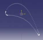
I am a new guy starting using CATIA to draw an airfoil. However, I faced the problem that I have goolged it but couldn't found any clues: the spline created could not match well to points provided. I hope that I can get your supporting advice.

I imported coordinates from Excel to CATIA, it seemed good. Then I follow steps in this video, from 10:30.
https://www.youtube.com/watch?v=vaMsdtgEXvs#

I attache here my dropbox link, picture for your reference: https://www.dropbox.com/sh/511q0o0999jkew2/AACqwXo-WdPVY5g1_28uXDZYa?dl=0
Screenshot 2016-07-13 23.17.27.jpg

I found that for much simpler curve like 3 or 4 points defined spline, it still works. But for the airfoil, it fails.

Thank you very much for your help.
 
Last edited:
Instead of just one spline, I would make 3 splines. 1. Leading Edge, 2. Top surface, 3. Bottom surface. And if necessary a line for the trailing edge surface.
 
Hi MrCATIA,

Thanks for your idea. But I just tried it again for leading edge and trailing edge of the turbine, it didn't work as well. :(Screenshot 2016-07-14 04.46.47.jpgScreenshot 2016-07-14 04.48.20.jpg
 
Hi MrCATIA,

According to the tutorial, I made it from Spline option in Wireframe and Surface Design mode (I also tested with Generative Shape Design already, but it didn't work as well). How can I choose 3D spline with support?
The tutorial is here, from 10:30 https://www.youtube.com/watch?v=vaMsdtgEXvs

These points come from the turbine blade profile of NASA. http://ntrs.nasa.gov/search.jsp?R=19900019237

I would like to create the curve that form an airfoil based on points coordinate provided. I think it is very popular in airfoil drawing. :(

My files on dropbox is here: https://www.dropbox.com/sh/511q0o0999jkew2/AACqwXo-WdPVY5g1_28uXDZYa?dl=0

P/s I cannot attach the drawing file on forum.
 
Last edited:
Did you try adjusting the Accuracy setting in Tools + Options?

Thanks for all the responses and info. You should be able to fit a nice spline(s) through the points, and then I suggest smoothing the splines with the SMOOTH CURVE tool that in the GSD2 license.

I'm busy at work right now and I normally don't like to download CAD files or data from the internet, but I will try to fit some splines through your data in a couple days.
 
After adjusting accuracy, it is much better. However, there are still some points that the curve does not match. Maybe a stupid question, but I don’t see it was mention in CATIA documentation about the dimension of this accuracy? Or is it a mathematic definition of “tessellation”?
I observe that this turbine has high curvature with high points density (162 points per 2.5cm chord). Can CATIA fit better? If not, is there the reason that CATIA perform well for external aerodynamics in which chord is in meter size? And engine manufacturers prefer Siemens NX which performs better at cm size?
If it does not perform well in cm size, should I exaggerate the size, then I scale down it later in CFD software?
However, I noted that it is interesting that the region where the curve does not fit well to points lie in the leading edge where has much lower curvature than the trailing edge where it fits well.
Could you explain to me?

Let me try with the Smooth Curve tool, it seems a little bit complex.
 

Attachments

  • Screenshot 2016-07-15 05.14.34.jpg
    Screenshot 2016-07-15 05.14.34.jpg
    21.6 KB · Views: 8
That is a small turbine blade! Did you try setting the display accuracy to Proportional? I like you idea of scaling up the size, and seeing if that improves the curves. I also suggest trying to make the spline by using every other point (or every third point or fourth point) and verifying the path with the the unused points.

A CATIA Spline is defined mathematically to go through each point. It's not a best fit, but an exact fit. But the smoothing process will result in a curve that has some deviation from the points.
 
Dear MrCATIA,

Yes, I tried changing the default setting into "proportional".
Sorry for just being a newbie, I have not been familiar with CATIA words yet. As I understand, " using every other point (or every third point or fourth point)" means choosing the next 3rd or 4th point and see if it fits the rest?

Sometimes I feel that when I ignore some points, the curve looks nicer, less wiggles. Do you think it is better? I mean the original, physical turbine is smooth, then they got the coordinates and give them to us. But when we recreate the airfoil again, somehow wiggles appear.
 
Yes, that is what I meant. When fitting curves to points (I think this is called "lofting"), the fewer points will give you smoother curves. More points will force the curve to wiggle. So by skipping some of the points, you will probably get a much smoother spline.

A good tool to use to check the "smoothness" spline (or any curve) in CATIA is the Porcupine Analysis.
 
I was unable to download the data from Dropbox. But I was able to simulate your problem by making alot of points on a Ø20mm circle.

My spline looked smooth at first. But when I started zooming in to pick more points, I started to see where the curve was no longer passing through all the points, similar to the original pictures you posted. When I changed the display accuracy setting, I was to vary the number of vectors that represented the spline.

So, my conclusion is your spline is good and it passes through all the points. The minimum display accuracy setting is 0.01, and even that setting caused the spline to appear to come off the points. The proportional option did not seem to help.

If you only have one spline, the Smooth Curve tool won't do much since a spline is smooth to begin with. However, if you join 2 or 3 splines together (and introduce discontinuities between the curves), then the Smooth Curve tool will eliminate the discontinuities. I used the Porcupine Analysis to verify the changes.

Another thought: Verify the CATIA units you are working with and verify that the point coordinates are in the correct units. I've seen in the past where importing points from Excel will read inch data as mm, and the data will be 25.4 times smaller. This could cause the display accuracy to be worse.
 
Last edited:
Hi Giang, I'm Vietnamese.
Could you follow this video on my channel.
Your problem can solve at 8:24, change from 1 -> 2 for points and Spline.
 

Articles From 3DCAD World

Sponsor

Back
Top